


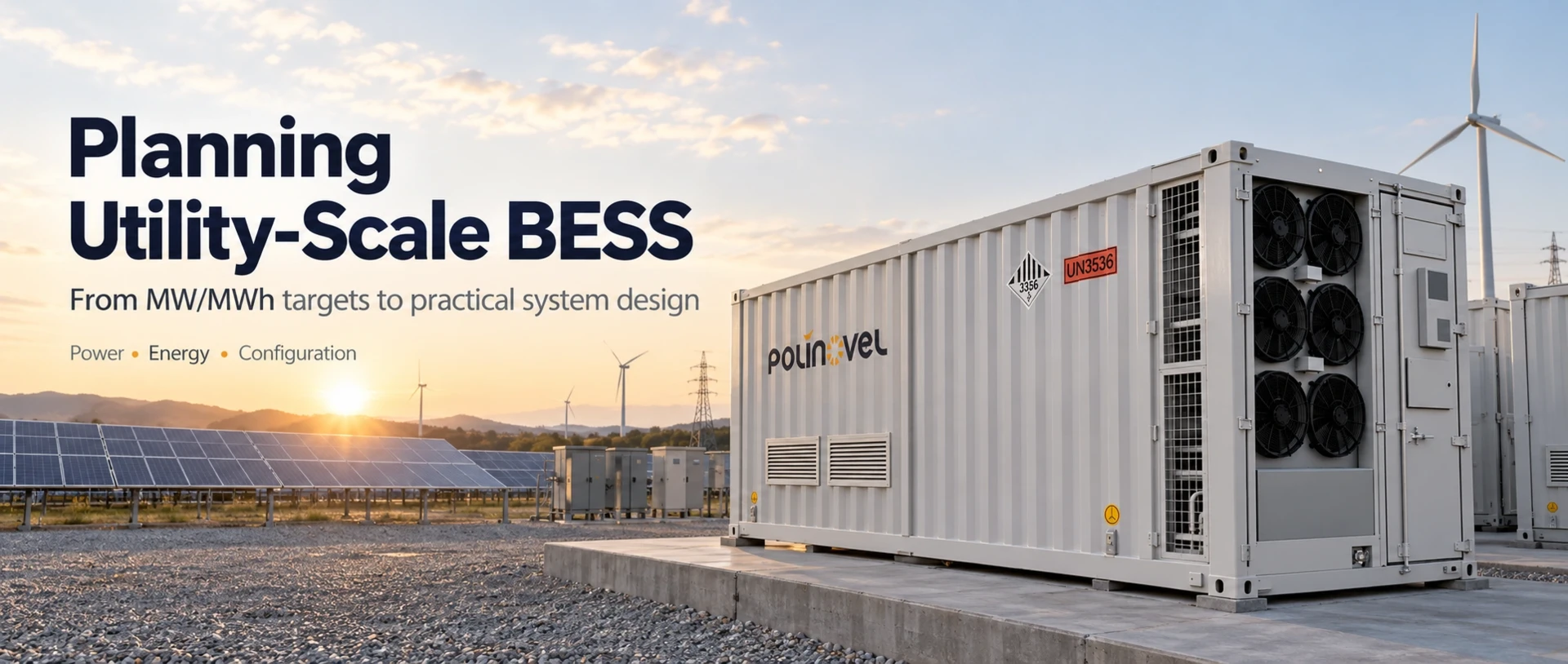
Consider a hypothetical case: a developer is planning a 100 MW / 400 MWh utility-scale battery storage project. On paper, the requirement looks clear. But before selecting battery containers or sizing the PCS, several project conditions still need to be defined.
Where is the 400 MWh measured? How much usable energy must be available over the project life? What grid and site conditions will the system need to meet?
Using this illustrative project, this article shows how utility-scale BESS sizing moves from an initial MW/MWh requirement to a practical system configuration.
The example provides a general sizing framework; the final BESS configuration will depend on the project's actual performance requirements, grid conditions, site constraints, and operating strategy.
Start With the Utility-Scale BESS Design Basis
A utility-scale battery storage project usually starts with a power and energy requirement. In our illustrative case, the target is 100 MW / 400 MWh, which gives a nominal storage duration of four hours: 400 MWh ÷ 100 MW = 4 hours
The U.S. Energy Information Administration (EIA) defines battery duration as the ratio of energy capacity in MWh to power capacity in MW. In practice, however, this four-hour figure is only the nominal duration at rated power.
That calculation defines the basic performance target. It does not yet tell us how much battery capacity should be installed, how the PCS should be sized, or how many BESS blocks the project will need.
Before those decisions can be made, the design basis has to answer several practical questions:
- Is the 400 MWh requirement measured at the battery DC side or at the AC delivery point?
- How often will the system charge and discharge?
- What capacity must still be available near the end of the project life?
- What grid voltage and operating requirements apply?
- What site conditions could affect cooling, derating, or layout?
These details matter because they change different parts of the design. A stricter end-of-life requirement may increase the installed battery capacity. A different grid connection may change the PCS, transformer, and MV configuration. High temperatures or limited site space can also affect equipment selection and layout.
So even if two projects are both rated at 100 MW / 400 MWh, their final BESS configurations may not be the same.
Determine the Battery Capacity the Project Actually Needs
For a utility-scale battery storage project, the required MWh is only the starting point for battery sizing. A 400 MWh project does not necessarily mean installing exactly 400 MWh of battery nameplate capacity.
The actual requirement depends on three key factors:
1. Where Is the Energy Measured?
The first step is to define the energy measurement boundary - the point in the system where the required MWh is measured.
A 400 MWh requirement may refer to:
- Battery DC-side energy - energy available before power conversion; or
- AC delivered energy - energy available after conversion and delivered toward the grid.
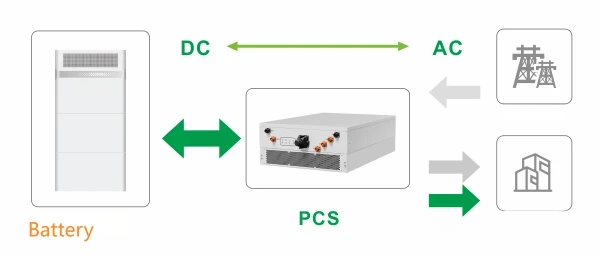
These are not the same sizing basis. If the project must deliver 400 MWh on the AC side, the battery also needs to account for losses through the PCS - the power conversion system that converts DC battery power to AC, the transformer, and other parts of the power path.
2. How Much of the Installed Capacity Is Usable?
Battery nameplate capacity is not always equal to usable project energy.
A BESS normally operates within a defined SOC window - the permitted operating range between minimum and maximum state of charge. The usable energy can also be affected by:
- Depth of discharge (DoD) - how much of the battery capacity is used during a cycle;
- charge and discharge limits;
- operating strategy;
- temperature and system conditions.
So the more useful sizing question is not simply "How many MWh are installed?" but "How many MWh can the system reliably deliver under the required operating conditions?"
3. What Losses and Auxiliary Loads Must Be Included?
Not all stored energy reaches the grid. Some is lost during conversion, while some is consumed by the BESS itself.
Typical contributors include:
- PCS conversion losses;
- transformer losses;
- liquid cooling or HVAC;
- auxiliary loads - energy consumed by pumps, controls, cooling, and other supporting equipment.
EPRI's guidance on BESS usable energy similarly distinguishes installed battery capacity from the energy ultimately delivered at the point of interconnection, accounting for DC and AC losses, auxiliary consumption, operating margins, and degradation.
For this project, the sizing logic is closer to: Required deliverable energy → measurement boundary → usable energy → system losses and auxiliary loads → installed battery capacity
This establishes the beginning-of-life (BOL) capacity required at commissioning. Final sizing must also account for how much capacity the system needs to retain over the project life.
Account for Degradation and End-of-Life Battery Capacity
1. Define the End-of-Life Requirement
End-of-life (EOL) capacity - the capacity the battery is expected to retain near the end of the specified project life - is an important sizing input.
For example, two projects may both require 100 MW / 400 MWh, but their initial installed capacity may differ if:
- one project only needs to meet the target at commissioning;
- the other must still deliver the required usable energy after 10, 15, or 20 years.
The second project may require more initial battery capacity or a planned augmentation strategy.
2. Consider How the Battery Will Be Operated
Battery degradation depends on more than project age. It is also influenced by the operating profile, including:
- cycle frequency - how often the battery charges and discharges;
- depth of discharge (DoD) - how much capacity is used in each cycle;
- SOC window - the permitted operating range between minimum and maximum state of charge;
- charge and discharge rate;
- operating temperature;
- calendar aging - capacity loss that occurs over time even when the battery is not cycling heavily.
Two projects using the same battery technology can therefore follow different degradation paths if their cycling frequency, DoD, SOC range, temperature, or charge/discharge rates are different.
3. Choose Between Initial Oversizing and Augmentation
There are two common ways to account for future capacity loss:
- Initial oversizing - installing additional battery capacity at the start of the project;
- Augmentation - adding battery capacity later as the original system degrades.
The right approach depends on project life, warranty conditions, available site space, operating profile, and project economics. These factors also influence the wider sizing and technology decisions in a grid-scale battery storage project.
For this reason, two suppliers may propose different installed MWh for the same nominal 100 MW / 400 MWh project. The key is not simply which proposal has more battery capacity, but what degradation assumptions, EOL target, and augmentation strategy are behind that number.
Choose the BESS Architecture Before Counting Containers
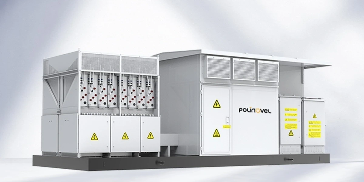
In utility-scale battery storage, battery capacity is only one part of the equipment configuration. The project team also needs to decide how the battery, PCS, transformer, and grid-side equipment will be integrated.
DC-Side Battery Container Architecture
In a DC-side architecture, the container mainly provides battery energy storage. The PCS, transformer, and medium-voltage equipment are configured separately. A typical power path is: Battery Container → External PCS → Transformer / MV Equipment → Grid.
This approach may suit projects where the EPC has already selected the PCS or where the battery, power conversion, and grid-side equipment need to be specified independently.
For example, Polinovel's DC-side battery storage container does not include a built-in PCS and is designed to work with external power conversion and grid-side equipment according to the project's voltage, power, and interconnection requirements.
Integrated Containerized BESS Architecture
An integrated system combines more functions within each BESS unit. Depending on the design, this can include the battery, PCS, EMS, thermal management, fire protection, and communication systems. The power path becomes more integrated: Integrated BESS → Transformer / MV Interface → Grid.
This can reduce the number of equipment interfaces that need to be coordinated on site and make it easier to repeat the same system block across a large project.
Polinovel's 6.25 MWh containerized BESS, for example, integrates the battery, PCS, EMS, liquid cooling, fire protection, and communication systems within a 20-foot container.
Which Architecture Fits the Project?
The choice depends on what has already been defined at the project level:
| Project Situation | Configuration Direction |
| PCS and EMS are already specified | DC-side battery container |
| Battery and power conversion need separate selection | DC-side battery + external PCS |
| Standardized AC/DC blocks are preferred | Integrated containerized BESS |
| PCS, transformer, and MV equipment need packaged | Battery system + PCS container / project-specific block |
This is also why MWh alone is not enough to compare BESS containers. A 5–6 MWh DC battery container and a 5–6 MWh integrated BESS are not equivalent products. The comparison also needs to consider PCS power, usable energy, voltage range, integration scope, efficiency, and the required grid-side equipment.
For this project, container quantity should only be calculated after the system architecture has been selected. Battery MWh can then be matched with the required PCS capacity and organized into practical BESS power blocks.
Match Battery MWh With PCS MW and BESS Power Blocks
Battery MWh and PCS MW represent different design constraints and must be matched at the system level:
- Battery energy (MWh) - defines how much energy is stored. The actual usable or deliverable energy also depends on the SOC window, system losses, operating limits, and the agreed measurement point.
- PCS power (MW) - defines the system's active power conversion capability. At the plant level, however, the final PCS configuration also needs to account for apparent power (MVA), reactive power requirements, transformer capacity, the point of interconnection (POI), and any site-related derating.
For the illustrative 100 MW / 400 MWh project, having enough battery energy does not by itself guarantee that the plant can deliver 100 MW at the required grid connection point. The PCS and AC-side equipment must also be sized to meet the required active power while supporting the project's reactive power and grid requirements.
Temperature, altitude, and other site conditions may also reduce the available PCS or transformer output if derating applies. For this reason, the final power-block design should be checked against the required performance at the POI, rather than against the PCS MW rating alone.
From Containers to BESS Power Blocks
At utility scale, battery containers are rarely considered as isolated units. They are usually grouped with power conversion and grid-side equipment into repeatable BESS power blocks - modular sections of the plant with a defined MW and MWh rating.
A typical block may include: Battery System → PCS → Transformer → MV Switchgear
The size of each block depends on several factors:
- battery energy available per block;
- PCS MW/MVA rating and DC voltage range;
- reactive power and POI requirements;
- transformer capacity;
- cable and current limits;
- temperature or altitude derating;
- redundancy requirements;
- site layout and maintenance strategy.
At the project level, the selected power blocks must collectively satisfy both the required MW and MWh targets. Adding battery MWh can extend storage duration, but it does not increase block MW unless the PCS and other AC-side equipment can support the additional power. The final number and size of the blocks therefore depend on both the battery and PCS configuration.
100 MW / 400 MWh Example: From Project Target to BESS Configuration
For the illustrative 100 MW / 400 MWh utility-scale battery storage project, the first calculation is straightforward: 400 MWh ÷ 100 MW = 4 hours
But this only defines the nominal power and energy target. The actual BESS configuration takes shape as each project condition is confirmed.
| Design Step | 100 MW / 400 MWh Example | Configuration Impact |
| Power requirement | 100 MW AC | The PCS and AC-side equipment must collectively support the required project power. |
| Energy requirement | 400 MWh | Defines the required energy target, but not necessarily the battery nameplate capacity. |
| Storage duration | 4 hours nominal | Establishes the basic energy-to-power ratio of the project. |
| Energy measurement point | Confirm DC-side or AC-delivered energy | If 400 MWh must be delivered on the AC side,conversion losses and auxiliary consumption must be included when sizing the battery. |
| Usable energy | Confirm SOC window and operating limits | Determines how much installed battery capacity is needed to provide the required usable energy. |
| EOL requirement | Confirm required capacity at the end of project life | May require additional initial capacity, future augmentation, or a combination of both. |
| System architecture | Select DC-side battery containers or an integrated BESS configuration | Determines how the battery, PCS, transformer, and MV equipment are arranged. |
| BESS power blocks | Match battery MWh with PCS MW | Defines the practical MW/MWh rating of each repeatable project block. |
| Container quantity | Calculated after unit capacity and architecture are selected | Becomes an output of the design rather than the starting assumption. |
So the configuration process can be summarized as: 100 MW / 400 MWh target → energy basis → usable and EOL capacity → system architecture → PCS and power-block sizing → final container quantity.
If 400 MWh is an AC-delivered requirement, the installed battery capacity will normally need to be higher than 400 MWh to account for usable-energy limits, conversion losses, and auxiliary consumption. If the project must also maintain the required energy at end of life, degradation must be addressed through additional initial capacity, future augmentation, or both.
If the 400 MWh value instead refers to battery-side nameplate capacity at the beginning of life, the sizing basis will be different.
This is why two projects with the same 100 MW / 400 MWh headline rating can result in different installed MWh, container counts, and PCS configurations.
What to Check Before Finalizing a Utility-Scale BESS Proposal
Two BESS proposals with the same MW/MWh rating may still rely on different design assumptions. Before comparing equipment quantity or price, confirm that both proposals are based on the same project requirements.
| Check | What to Confirm |
| Energy Basis | Is the quoted MWh nameplate, usable DC energy, or AC deliverable energy? |
| BOL/EOL Capacity | Is the capacity guaranteed at commissioning or at the end of project life? |
| PCS Rating | Does the PCS provide the required charge and discharge power? |
| System Scope | Are PCS, transformer, MV equipment, EMS, cooling, and fire protection included? |
| Degradation Strategy | Is future capacity loss covered by oversizing, augmentation, or both? |
| Grid & Site Conditions | Are grid voltage, temperature, altitude, and site constraints based on the actual project? |
A proposal with more installed MWh is not necessarily oversized, and one with less capacity is not automatically more efficient. The difference may come from the energy boundary, usable capacity, degradation assumptions, or integration scope.
The key is to compare each proposal on the same performance requirements and project conditions.
For the hypothetical 100 MW / 400 MWh utility-scale battery storage project, MW and MWh define the target, not the final BESS configuration.
Installed capacity, PCS sizing, system architecture, grid connection, and site conditions all need to be considered together.
Planning a utility-scale BESS project? Share your target MW, MWh, storage duration, grid voltage, and site conditions with Polinovel. Our team can help evaluate the battery capacity, PCS configuration, and system architecture for your project.