


A stationary battery energy storage system (BESS) for an EV fleet depot should be sized against two separate requirements: the highest power shortfall between charging demand and the permitted grid import, and the total energy the battery must deliver before it can recharge. Vehicle arrival and departure times determine when charging is needed; charger power, available charging ports, facility loads and the utility connection determine the size of the shortfall.
Charger nameplate power alone is not enough to select a battery. A depot with a long overnight dwell period may be able to meet much of its demand through managed charging. A depot that needs vehicles ready soon after arrival may require a higher-power BESS to support concentrated charging sessions. The design should therefore begin with the fleet operating schedule, not a predetermined battery capacity.
For commercial and industrial sites, the BESS can be evaluated as part of a wider commercial and industrial energy storage solution. The final configuration must still be based on the site's measured load profile, utility conditions and vehicle-readiness requirements.
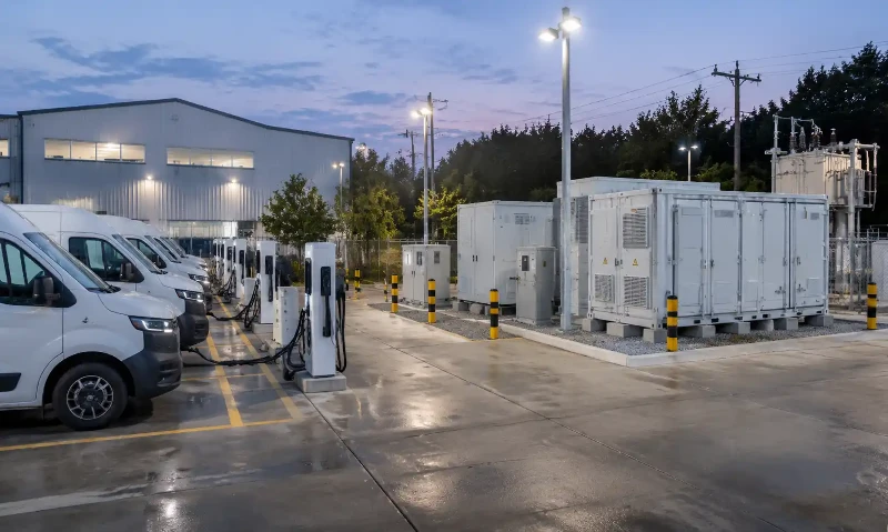
Why EV Fleet Charging Depots Need a Different BESS Sizing Approach
Fleet charging demand follows vehicle duty cycles
Public charging stations often serve drivers whose arrival times and charging durations vary throughout the day. A fleet depot has a different operating pattern. Delivery vans, buses, service vehicles and trucks may return within a relatively narrow time window and leave again at fixed dispatch times. When several vehicles connect at once, the depot can experience a concentrated load even if its total daily energy consumption is manageable.
The relevant design questions are how much energy each vehicle needs, how long it remains parked, how many vehicles can charge simultaneously and when each vehicle must be ready. A vehicle that returns with a low state of charge and leaves early may need priority over one that has a later departure or a shorter route the next day.
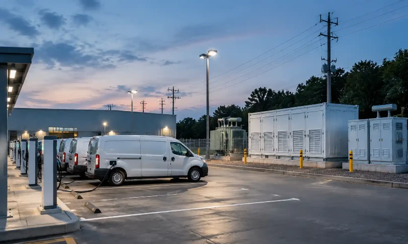
Grid capacity must cover the whole site, not just the chargers
The utility import limit is shared by EV charging equipment and the facility's other electrical loads. Lighting, HVAC, workshops, pumps, office equipment and other site loads reduce the power available to the chargers. The BESS must be sized against the total site demand at the point of connection.
A transformer nameplate is not automatically the site's permitted active-power limit. Transformer capacity is commonly stated in kVA, while charging demand is usually discussed in kW. Power factor, existing transformer loading, switchgear ratings, protection settings, service conductors and the utility's approved import limit all affect the usable capacity. Confirm the actual operating limit with the electrical engineer and utility before calculating the battery requirement.
Managed charging should be assessed before adding storage
Charging schedules, power sharing and staggered departures can reduce the peak without a battery. If the available dwell time is long enough, the fleet may be able to charge within the grid limit by lowering charger power or changing the order of charging sessions. A BESS becomes more valuable when the fleet needs a higher charging rate, the available charging window is short, or the site must keep grid import below a firm limit while meeting dispatch deadlines.
The U.S. Department of Energy's fleet charging guidance recommends assessing vehicle use, charging needs, utility capacity and demand charges together. That is the right starting point for a depot BESS study.
What Data Is Needed to Build an EV Depot Load Profile?
Build the load profile from actual fleet and facility information wherever possible. The National Renewable Energy Laboratory's depot-based vehicle charging analysis uses operating patterns, dwell durations and vehicle characteristics to develop charging load profiles. A project-level study should apply the same time-based approach to the specific vehicles and site being designed.
Collect vehicle and operating-schedule data
- Fleet inventory: vehicle type, quantity, battery capacity, vehicle model and expected daily duty cycle.
- Arrival and departure times: actual depot arrival, plug-in time, planned departure and the minimum readiness deadline for each vehicle.
- Daily energy requirement: route distance, energy use, auxiliary loads, initial state of charge and target state of charge.
- Charging flexibility: whether charging can be delayed, reduced or interrupted without affecting the next route.
- Operational variation: weekday and weekend differences, seasonal routes, unusually demanding days and planned fleet expansion.
Use vehicle telematics, charger records and route data to estimate the energy required for each charging session. If the EMS is expected to use live vehicle state of charge, confirm that the vehicle, charger and software interfaces actually make that information available. Do not assume that a charging cable or a particular OCPP version automatically exposes every vehicle battery parameter.
Confirm charger capability and port availability
Record the number of charging positions, each charger's rated power, its AC input demand, connector configuration, power-sharing capability and the vehicle's maximum accepted charging rate. The charger rating is a ceiling, not proof that every connected vehicle will continuously draw that amount. Vehicle charging curves, battery temperature, state of charge and charger power allocation can all change the actual load.
Polinovel's EV charger range provides a reference for the charging equipment side of a project. For a real depot, match charger selection to the fleet's vehicle specifications and required turnaround time rather than selecting chargers by maximum output alone.
Measure the facility load and confirm the grid limit
Obtain interval data for the existing facility load, preferably covering representative operating days and seasonal conditions. Identify the site's maximum permitted grid import, transformer and switchgear constraints, demand-charge measurement interval, time-of-use tariff and any export restrictions. If solar generation or another on-site generator is present, include its output profile and operating limits.
Use a time interval that captures the charging pattern and is consistent with the utility's metering and billing rules. A billing interval may be 15 minutes in one tariff and different in another. Shorter intervals may also be needed to check charger transients, control response and equipment limits.
How to Calculate the Required BESS Power Rating
Calculate the site power deficit at each time interval
At each time interval, add the EV charging load to the facility's non-EV load. Subtract the maximum permitted grid import. The positive difference is the AC power that the BESS or another controllable resource must supply if the site is to maintain the charging schedule without exceeding the grid limit.
Required BESS AC output at time t:
P_BESS,AC(t) = max[0, P_EVSE(t) + P_base(t) - P_grid,max]
- P_EVSE(t): total EV charging equipment demand at the site's AC bus.
- P_base(t): other facility demand at the same point of measurement.
- P_grid,max: permitted active-power import from the utility.
- P_BESS,AC(t): AC power required from the BESS during that interval.
The minimum AC discharge rating is the highest value of this deficit across the operating schedule. If the required output exceeds the PCS rating, the EMS must reduce charger demand, change the schedule or use another source of power. Increasing battery energy capacity does not solve an undersized PCS.
Check the PCS rating and continuous discharge duration
The power conversion system determines how much AC power the battery can deliver to the site. Specify the required continuous AC output and the duration for which it must be sustained. Also check the PCS kVA rating, power-factor requirements, reactive-power capability, overload duration, voltage range and thermal derating at the project's design ambient temperature.
The battery pack must support the corresponding DC discharge power at the required duration and operating temperature. For example, if the complete DC-to-AC discharge path is assumed to be 95% efficient, delivering 170 kW AC requires approximately 179 kW from the battery DC side. The actual value must come from the selected battery and PCS performance data.
Review the PCS operating envelope and conversion path before finalizing the battery. Polinovel's power conversion system overview provides additional background on the PCS role in a BESS.
How to Calculate Usable BESS Energy Capacity
Integrate the power deficit over the full charging schedule
Power determines how quickly the BESS must respond. Energy determines how long it must continue supplying that power. Calculate the area under the positive power-deficit curve across the full period between recharge opportunities.
Required AC discharge energy:
E_BESS,AC = Σ [P_BESS,AC(t) × Δt]
Use the actual time-series profile rather than multiplying the maximum power by the entire parking period. The maximum deficit may last for only part of the night, while later charging sessions may fit within the grid limit.
Convert AC delivery into battery nameplate capacity
The required AC energy is not the same as the battery's DC nameplate capacity. The design must account for the usable state-of-charge window, capacity retention at the end of the design life and losses between the battery DC terminals and the AC bus.
Illustrative battery nameplate calculation:
E_nameplate,DC ≥ E_BESS,AC ÷ (SOC_usable × SOH_EOL × η_discharge,DC-to-AC)
- SOC_usable: the permitted operating state-of-charge window, expressed as a fraction of nameplate capacity.
- SOH_EOL: the guaranteed capacity retention at the selected end-of-life point.
- η_discharge,DC-to-AC: the efficiency from the battery DC side to the AC delivery point, including the losses included in the project boundary.
Auxiliary loads from cooling, pumps, controls and other equipment should be added where they are not already included in the measured energy boundary. Any emergency reserve or minimum SOC requirement must also be reflected in the usable energy calculation. Do not apply a generic percentage without checking the actual equipment and operating conditions.
Check the recharge window before approving the capacity
A BESS that can discharge through the evening peak may still be unsuitable if it cannot recharge before the next fleet cycle. Calculate the AC energy required to restore the battery and compare it with the grid capacity available during the recharge window.
If charge-path and discharge-path efficiencies are modeled separately, a simplified recharge calculation is:
E_AC,recharge = E_AC,discharged ÷ (η_charge × η_discharge)
This expression excludes auxiliary consumption unless it is included in the efficiency values. Add the actual auxiliary energy separately where necessary. Then confirm that the available charging power, battery charge acceptance and remaining time can restore the required SOC before the next dispatch period.
Worked Example: Sizing a Stationary BESS for a 20-Van Depot
The following is a hypothetical engineering example designed to show the calculation method.
Define the fleet schedule and site constraints
| Parameter | Illustrative value |
|---|---|
| Fleet size | 20 electric vans |
| Charging energy per van | 80 kWh at the EVSE AC input |
| Total daily EV charging energy | 1,600 kWh |
| Depot arrival | 19:00 |
| Next departure | 07:00 |
| Available charging positions | 6 |
| AC input demand per active position | 50 kW |
| Maximum grid import | 150 kW |
| Facility baseline load | 20 kW |
| Grid capacity available to EVSE and BESS | 130 kW after baseline load |
| Early fleet-readiness target in this scenario | 01:24 |

The 80 kWh per van is treated as energy measured at the charger AC input. If 80 kWh instead represents energy stored in each vehicle's traction battery, convert it to the required AC input using the actual charger and vehicle charging efficiency before applying this model.
The operator wants all 20 vans ready by 01:24, rather than using the entire 12-hour parking window. This early-completion target creates a higher charging peak than a schedule that spreads charging until 07:00.
Build the charging sequence
Each active charging position draws 50 kW AC. One van therefore requires 1.6 hours to receive 80 kWh at the assumed input boundary. With six available positions, the depot can charge three groups of six vans and a final group of two.
| Charging batch | Time | Vehicles charging | EVSE demand | Energy delivered |
|---|---|---|---|---|
| 1 | 19:00–20:36 | 6 | 300 kW | 480 kWh |
| 2 | 20:36–22:12 | 6 | 300 kW | 480 kWh |
| 3 | 22:12–23:48 | 6 | 300 kW | 480 kWh |
| 4 | 23:48–01:24 | 2 | 100 kW | 160 kWh |
| Total | 19:00–01:24 | 20 | - | 1,600 kWh |
Calculate the required BESS power
During the first three batches, six vans draw 300 kW. Adding the 20 kW facility baseline produces a total site demand of 320 kW. The utility can supply 150 kW, so the BESS must provide the remaining 170 kW AC.
P_BESS,AC = 300 kW + 20 kW - 150 kW = 170 kW
This peak lasts for three consecutive 1.6-hour batches, or 4.8 hours. During the final batch, two vans draw 100 kW. Including the 20 kW baseline, total site demand is 120 kW, which is below the 150 kW grid limit. The BESS does not need to discharge during that final batch.
The PCS must therefore deliver at least 170 kW AC continuously for 4.8 hours under the project's design conditions. The final PCS rating should also account for power factor, reactive power, temperature derating and any required operating margin.
Calculate the AC energy the BESS must deliver
The BESS supplies 170 kW during the 4.8-hour high-power period:
E_BESS,AC = 170 kW × 4.8 h = 816 kWh
The grid supplies 130 kW to the EVSE during the same 4.8-hour period, or 624 kWh. During the final 1.6-hour batch, the grid supplies the full 100 kW EVSE demand, or 160 kWh. Total direct grid energy delivered to the chargers is therefore 784 kWh.
Grid-to-EV energy = 624 kWh + 160 kWh = 784 kWh
Total EV energy = 784 kWh + 816 kWh = 1,600 kWh
The charging energy balance now matches the 20-van requirement without counting the same grid energy twice.
Estimate the battery nameplate capacity
For this example, assume an 80% usable SOC window, 80% capacity retention at the selected end-of-life point and 95% efficiency from the battery DC side to the AC bus. These are modeling assumptions, not universal battery specifications or a Polinovel product guarantee.
E_nameplate,DC = 816 ÷ (0.80 × 0.80 × 0.95)
Calculated battery nameplate capacity: approximately 1,342 kWh, or 1.34 MWh.
At the assumed 95% DC-to-AC discharge-path efficiency, the battery must supply approximately 179 kW DC to deliver 170 kW AC. The battery cells, DC bus and protection equipment must be rated for that power over the required discharge duration.
Verify the next recharge window
Assume the AC-to-DC charge-path efficiency is also 95%. Replacing the 816 kWh AC discharge requires approximately 904.2 kWh of AC input before additional auxiliary consumption:
E_AC,recharge = 816 ÷ (0.95 × 0.95) ≈ 904.2 kWh
After the vans leave at 07:00, the 20 kW facility baseline leaves up to 130 kW of grid capacity available for BESS charging. At that power, the theoretical recharge time is:
Recharge time = 904.2 kWh ÷ 130 kW ≈ 6.96 hours
The 12-hour daytime window is long enough under these assumptions. The actual design must also include BESS auxiliary consumption, charge-power limits, temperature-related derating and any other loads that share the connection.
Review the complete 24-hour operating profile
| Time period | EVSE demand | Facility load | Grid import | BESS operation |
|---|---|---|---|---|
| 19:00–23:48 | 300 kW | 20 kW | 150 kW | Discharge 170 kW AC |
| 23:48–01:24 | 100 kW | 20 kW | 120 kW | No discharge required |
| 01:24–07:00 | 0 kW | 20 kW | 20 kW | Idle or maintain reserve SOC |
| 07:00–19:00 | 0 kW | 20 kW | Up to 150 kW while charging | Recharge at up to 130 kW AC |
This schedule demonstrates why power and energy must be checked separately. The BESS needs a 170 kW AC output to cover the peak, but it must deliver 816 kWh over the complete high-demand period and recover that energy before the next fleet cycle.
Compare the fast-turnaround schedule with managed charging
The 1.34 MWh result is specific to the early-completion schedule above. It is not automatically required for the same 20 vans if the depot can use the full 12-hour dwell period and reduce charger power.
For comparison, assume five charging positions can each operate at approximately 26.7 kW AC. Four groups of five vans can then charge for three hours per group. The combined EVSE demand is about 133.3 kW, only 3.3 kW above the 130 kW available from the grid after the facility baseline. Across 12 hours, the theoretical AC energy shortfall is about 40 kWh.
Under the same 80% usable SOC, 80% end-of-life capacity and 95% discharge-path assumptions, that energy shortfall corresponds to approximately 66 kWh of battery nameplate capacity before auxiliary loads and practical design margins. Such a small calculated requirement may not justify a dedicated BESS; a minor increase in grid capacity, a longer dwell window or a different charger allocation may be more practical.
This comparison is the key sizing lesson: the charging policy changes the BESS requirement. A fast-turnaround fleet may justify a larger battery, while a depot with flexible departures and effective power sharing may need little storage or none at all. Confirm minimum charger power, vehicle acceptance, port availability and readiness margins before choosing between the two schedules.
How EMS Coordinates Vehicle Charging and BESS Dispatch
Prioritize vehicles by energy need and departure time
The energy management system should use each vehicle's required energy and time remaining before departure to determine charging priority. A vehicle with a short dwell period and a high energy deficit may need a larger share of the available charging power than a vehicle that can remain connected for several more hours.
The controller should update the schedule when vehicles arrive late, depart early, require additional route energy or become unavailable. It should also account for charger faults and changes in facility load so that the planned charging profile remains achievable.
Coordinate EVSE demand with the grid import limit
The EMS should monitor the site meter, facility load, charger status, BESS SOC and PCS operating limits. When EV charging demand approaches the grid import ceiling, the controller can increase BESS discharge within the available power and SOC limits, reduce charger output or delay lower-priority sessions.
The U.S. Department of Energy's smart charge management guidance for federal fleets describes the data and coordination needed across fleet schedules, EV charging equipment, building loads and utility rate structures. It also identifies OCPP and OpenADR as communication standards that can support managed charging and interoperability.
Verify communication between the chargers, EMS and BESS
OCPP provides communication between charging stations and charging management systems. The Open Charge Alliance OCPP documentation describes smart-charging functions and the differences between supported protocol versions. However, OCPP support alone does not guarantee that a charger, fleet telematics platform and BESS controller can exchange every required data point.
Confirm the exact interface and point list for each device. The project may require OCPP between the charging stations and charge management platform, a vendor-supported interface such as Modbus TCP between the PCS and plant controller, and an API or gateway for fleet schedules and telematics. Test command response, meter accuracy, communication-loss behavior, cybersecurity requirements and fallback operating modes during commissioning.
For a deeper explanation of the control layer, see Polinovel's overview of the battery energy storage system EMS.
Recharge according to the actual utility tariff
Schedule BESS charging around the site's real utility tariff, available grid headroom and the next fleet departure deadline. Peak and off-peak periods vary by utility, service territory, rate plan and season; there is no single weekday peak window that applies to every depot. The EMS should use the tariff in force at the project location and avoid charging the BESS when doing so would create a new site peak or interfere with vehicle readiness.
Maintain a defined SOC reserve only when the operating objective requires it. If the BESS is also expected to provide backup power, confirm that the system includes the required islanding controls, grid-forming capability where applicable, transfer equipment and protected-load design. A reserve SOC by itself does not make a grid-connected BESS capable of supplying a facility during an outage.
When a Stationary BESS Can Defer a Grid Upgrade
Use BESS when the main problem is a concentrated power peak
A stationary BESS can help when the depot has enough total grid energy available over the day but cannot draw that energy at the rate required during a short charging window. The battery charges when spare grid capacity is available and discharges when several vehicles need power at once. This can reduce the peak import requirement and may defer or reduce some electrical infrastructure upgrades, subject to utility approval and site engineering.
Do not use storage to disguise a daily energy shortage
A battery shifts energy between time periods; it does not create energy. If the fleet's daily charging requirement, facility consumption and storage losses exceed the energy the site can obtain during the available grid and generation windows, a BESS cannot close the long-term energy gap by itself. The project may need a larger utility connection, more charging time, additional on-site generation or a change to fleet operations.
Compare managed charging, BESS and grid reinforcement
| Option | Best fit | Main limitation to check |
|---|---|---|
| Managed charging without BESS | Long dwell periods, flexible departures and chargers that support power sharing | May not meet short turnaround times or high daily energy demand within the grid limit |
| Stationary BESS | Short-duration power peaks with enough time and grid headroom to recharge | Requires battery and PCS investment, usable-energy margin, thermal management and a workable recharge window |
| Grid capacity upgrade | Persistent import constraints or insufficient daily energy supply | Requires utility studies, equipment work, permitting and a project-specific delivery schedule |
Compare the options using the site's actual utility tariff and project costs. Include demand charges, energy charges, utility upgrade costs, BESS capital cost, conversion losses, maintenance, degradation, warranty limits, replacement assumptions and expected fleet growth. A BESS should not be described as automatically faster or cheaper than a grid upgrade; both cost and schedule depend on the location and project scope.
Frequently Asked Questions
How do you size a BESS for an EV charging depot?
Build a time-based EV charging and facility load profile, subtract the permitted grid import at each interval and identify the maximum power deficit. Integrate that deficit over the required discharge period to calculate AC energy, then convert it to battery nameplate capacity using the usable SOC window, discharge-path efficiency and end-of-life capacity requirement. Finally, verify that the battery can recharge before the next fleet cycle.
Is BESS power or energy capacity more important for EV fleet charging?
Both are required. Power in kW determines how much simultaneous charging demand the BESS can support. Energy in kWh determines how long it can sustain that output. A system with enough energy but an undersized PCS cannot cover the peak, while a high-power system with insufficient usable energy may stop supporting the depot before the charging sessions are complete.
Can a stationary BESS eliminate the need for a grid upgrade?
Not in every project. A BESS may reduce a short-duration peak if the site has enough grid energy and recharge capacity over the rest of the day. It cannot solve a persistent daily energy shortage or a connection constraint that remains active for most operating hours. Compare managed charging, storage and utility reinforcement using the actual load profile and utility requirements.
How much BESS capacity does a 20-vehicle depot need?
There is no standard capacity for a 20-vehicle fleet. The answer depends on energy required per vehicle, charger count and power, arrival and departure times, the permitted grid import, facility loads and the amount of charging that can be shifted. In the illustrative fast-turnaround case above, the calculated battery nameplate is about 1.34 MWh. A more flexible 12-hour charging schedule produces a much smaller theoretical deficit.
Does an EMS need OCPP 2.0.1 to manage fleet charging?
Not necessarily. The required OCPP version and smart-charging functions depend on the charging stations and management platform. Confirm the supported features, compatibility and certification status of the actual equipment. Also verify how the EMS exchanges data with the BESS controller and fleet telematics; OCPP alone does not guarantee every system-level integration.
Can a BESS provide backup power to the depot during a grid outage?
Only if the system is specifically designed and configured for that function. Backup operation may require islanding protection, transfer equipment, a grid-forming or backup-capable PCS, defined protected loads and an approved operating sequence. A grid-following BESS that is designed only for peak shaving should not be assumed to energize the depot during an outage.
Conclusion: Size the BESS Around Fleet Schedules and Grid Constraints
EV depot BESS sizing starts with vehicle energy requirements and the time available to charge. The load profile then reveals the maximum AC power deficit, the energy the battery must deliver and whether the site can recharge it before the next dispatch cycle. Managed charging should be assessed first, followed by BESS sizing and grid-upgrade analysis where the operating schedule still exceeds the available connection capacity.
For a project-specific configuration, Polinovel can review the fleet schedule, grid import limit, charger arrangement and required operating profile to assess a suitable commercial and industrial BESS. Contact the Polinovel team with the site's load data and charging requirements for a project-level discussion.