


BESS system integration connects the battery, power conversion equipment and controls with the site's electrical and operating requirements. Agreed interfaces define how commands, operating limits and equipment status move between systems, while commissioning checks how the connected equipment responds.
What Battery Energy Storage Integration Includes
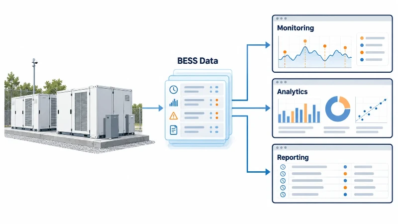
BESS system integration covers electrical connections, control functions, communications, auxiliary power and protection interfaces. The supply scope separates factory integration from the work needed to connect the equipment to the site. The battery energy storage system architecture identifies the main equipment and control relationships behind these interfaces.
Defining the internal equipment boundaries
Internal integration connects the battery modules, BMS, PCS and the supplied cooling, protection and control equipment. The factory configuration establishes internal wiring, communication settings, operating limits and equipment interlocks. Local protection functions follow the equipment design and remain independent of cloud availability. Authorized configuration changes are managed through the applicable access and version controls.
Managing the site integration responsibilities
Site integration connects the supplied BESS to project meters, switchgear, auxiliary supplies, the site controller and remote monitoring. The interface schedule identifies who provides field cables, protection connections, network settings and commissioning support. The allocation follows the agreed contract: the BESS supplier and EPC coordinate interfaces that cross their supply boundaries. Required emergency-stop circuits and shutdown sequences are defined in the project design.
Define the BMS, PCS and EMS Interfaces
Interface design establishes which device produces each signal, which controller receives it and which equipment executes the resulting action. The control architecture can use direct device links, gateways or a site controller, depending on the supplied equipment and project requirements.
Mapping the subsystem responsibilities
The BMS monitors battery voltage, current and temperature, estimates SOC and SOH, and provides the permitted operating limits and alarm states. The power conversion system (PCS) executes accepted charge and discharge commands within battery and converter limits and reports measured power and operating status. The EMS or site controller coordinates dispatch using site demand, metering and the selected operating strategy. Enable, standby, running, stopping and fault states are mapped between controllers so that a command is accepted only in an appropriate state.
Understanding the underlying data exchange mechanisms
Physical interfaces, communication protocols and application data are specified separately. A CAN connection requires compatible message identifiers, signal definitions and timing. Modbus integration requires agreed register addresses, function codes and data encoding. A gateway, where used, maps these definitions between systems. CAN message delivery depends on bus arbitration and loading; Modbus response timing depends on the implementation and polling design. The complete control path is assessed against the application's response requirements.
Agree the Communication Data Before Integration
Using the same protocol does not guarantee compatible data or control functions. The interface specification defines the points exchanged, their meaning and the conditions under which they can be used.
Specifying the data point attributes
A complete interface sheet lists signal names, data sources and receivers, units, scaling, charge/discharge sign conventions, access rights and protocol versions. For Modbus, it also identifies register types, addressing conventions and function codes. Byte order and, for values spanning multiple registers, word order are agreed at both ends. Readback checks confirm that values such as power, temperature and operating limits are interpreted correctly.
Aligning the update cycles and data validity
Source update rate, polling interval and recording interval are separate settings. Each signal has an agreed freshness limit and a method of detecting invalid or stale data, such as quality flags, timestamps, counters or timeouts. A successful network connection alone does not establish that the underlying measurement is current. Routine operating trends and high-speed fault records have different recording requirements. The following schedule illustrates the information to define; it is not a Polinovel product register map.
| Signal | Data path | Definition | Integration check |
|---|---|---|---|
| Battery SOC | BMS to controller | Unit, scaling, valid range and data quality | Readback, freshness and invalid-value handling |
| Charge and discharge limits | BMS to PCS or controller | Current or power basis, direction and update behavior | Accepted command remains within the active limits |
| Active power command | Authorized controller to PCS | Sign convention, unit, access rights and command validity | Command acceptance, measured output and limiting status |
| Site meter values | Meter to site controller | Meter location, CT ratio, phase mapping and import/export direction | Known-load comparison and meter-loss response |
| Equipment state and alarms | Equipment to site controller | State definitions, alarm identifiers, severity and reset conditions | Correct indication, event timing and alarm clearing |
| Emergency-stop status | Safety circuit or equipment to monitoring | Indication source and relationship to the designed stop circuit | Status indication agrees with the approved shutdown sequence |
Set Control Priority and Operating Limits
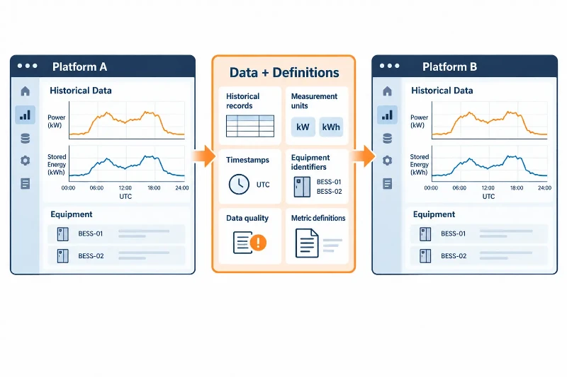
Control priority determines which source can issue commands and when authority can change. The controller reports the active control source and rejects commands that conflict with the selected operating mode or available equipment limits.
Enforcing the control hierarchy
Maintenance lockout, emergency controls, local operation, remote manual control and external dispatch have defined permissions and priorities. External dispatch remains subject to battery limits, PCS capability and site restrictions. When a request exceeds an available limit, the controls constrain the accepted command and report the limiting condition. Active and reactive power priorities follow the PCS capability and applicable grid requirements rather than a universal priority rule.
Separating dispatch from safety protection
Operating dispatch and safety protection have distinct functions. Protective actions follow the approved equipment and site design, including any required hardwired circuits. Temperature warnings, derating and shutdown are associated with their specified thresholds and operating states. Communication-loss behavior is defined separately for each interface: loss of a dispatch link, site meter or BMS connection can require different responses. The specification sets timeouts, permitted fallback operation and recovery conditions. Communication loss alone does not authorize islanded operation; that requires the designed isolation, controls and protection.
Test the Interfaces Before Site Handover
Interface tests check the functions required for the ordered configuration. The acceptance procedure identifies test conditions, measurement points, expected responses and pass criteria before factory or site testing begins.
Executing factory and site validation
Factory acceptance testing (FAT) checks the supplied equipment, internal connections, data mapping and agreed control functions within the factory test setup. Simulated signals can exercise selected logic where physical site equipment is unavailable. Site commissioning then checks actual meters, field wiring, switchgear and third-party controls. Communication and logic checks precede authorized energized tests. Factory testing does not replace tests that depend on the completed site installation.

Testing failure modes and alarm triggers
Tests compare requested power, accepted commands, measured output and active operating limits. They also check alarm mapping, communication loss and restoration, and the permitted restart sequence. Test records include configuration and software versions, synchronized timestamps appropriate to the test, equipment responses and unresolved deviations. The examples below define test topics; actual setpoints, timeouts and switching sequences belong to the approved project procedure.
| Test condition | Test action | Expected response | Record |
|---|---|---|---|
| Power dispatch | Issue charge and discharge commands within the test range | Accepted commands follow the agreed ramps and active limits | Commands, measured power and limiting conditions |
| Battery limit change | Apply an approved change to the permitted charge or discharge limit | Power is constrained by the new limit and the condition is reported | Limit values, timestamps and power trend |
| Communication or stale data | Interrupt a selected interface or apply an approved stale-data test | The specified timeout and fallback logic operate for that interface | Interface, timeout, fallback state and output |
| Emergency stop | Operate the emergency-stop input under the approved test procedure | The designed stop sequence and reset conditions are met | Alarm, relevant equipment states and reset result |
| Communication recovery | Restore the connection and valid data | Restart follows the required permissives, acknowledgement and ramp settings | Data validity, authorization and restart sequence |
Prepare the Integration Documents
The handover package records the interfaces and settings used for the delivered configuration. It supports commissioning, fault investigation, replacement equipment and controlled software changes.
Supplying the core engineering records
Polinovel provides equipment documentation and agreed factory test records for the supplied configuration. For example, the 125 kW / 261.2 kWh C&I cabinet lists CAN, Ethernet and RS485 communication interfaces. The project interface schedule identifies the supported protocol, accessible signals and control functions for the ordered configuration. Available ports alone do not establish compatibility with every external controller.
Tracking software versions and test results
The document register assigns responsibility for each deliverable. Equipment records are distinguished from site drawings and settings prepared by the EPC or other contractors. The agreed package covers the following items as applicable to the integration scope:
- Communication specifications with supported message or register definitions, data encoding and applicable function codes.
- Final data mapping with signal names, units, sign conventions, access rights, update settings and validity rules.
- Control narrative covering operating states, command authority, limits, communication-loss responses and recovery conditions.
- Alarm list with identifiers, severity, triggering conditions and equipment-specific troubleshooting guidance.
- Interface drawings identifying connections, terminal assignments, shielding and grounding requirements.
- Network configuration and access records with the agreed addressing, user permissions and remote-access arrangements.
- Software and firmware versions for the supplied BMS, PCS, controllers and gateways, including approved configuration backups.
- Completed test records identifying the tested configuration, results, deviations and acceptance status.
Firmware or component changes are checked against the interface baseline, with affected functions retested as required. For an integration review, send Polinovel your project interface requirements, including the existing PCS or EMS model, available protocol documents, site single-line diagram and required operating modes. We use these inputs to define the equipment configuration, interface scope and agreed factory tests.