


A battery energy storage project can have its battery containers and power conversion system installed and still be unable to energize. The step-up transformer, low- and medium-voltage switchgear, protection relays, metering, auxiliary power and grid-facing interfaces must also be designed, procured, tested and accepted before the plant can operate safely.
For utility-scale battery storage projects, these components are part of the electrical balance of plant, not peripheral accessories. Their ratings depend on the PCS operating envelope, grid connection voltage, reactive-power requirements, short-circuit conditions and protection philosophy. Their procurement and approval can also sit on the project critical path.
The practical question is therefore not simply which BESS transformer or switchgear lineup to buy. It is whether the complete AC and medium-voltage chain has been engineered from one controlled design basis so that every interface works together at energization.
Where Transformer and Switchgear Sit in the BESS Electrical Chain
A BESS moves energy through several electrical interfaces before it reaches the point of interconnection. The battery stores DC energy, the PCS converts it to AC, switchgear collects and isolates circuits, the transformer raises voltage, and the grid-facing protection and metering equipment connect the plant to the network.
The exact architecture varies by project, but a typical AC-coupled utility-scale path is:
Battery racks → PCS → LV AC collection and switchgear → step-up transformer → MV switchgear → protection and metering → main transformer or substation → point of interconnection
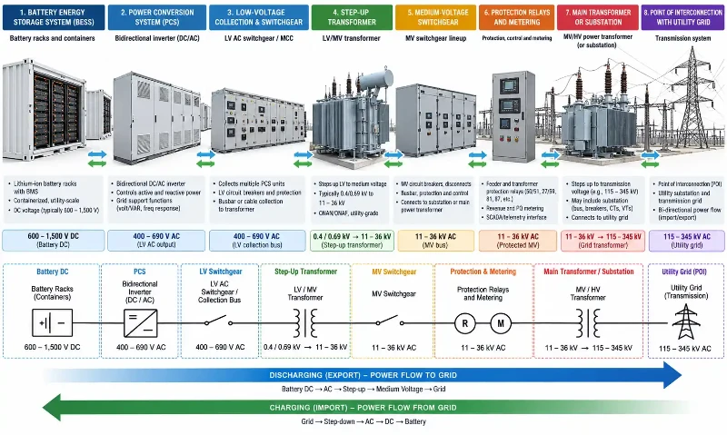
The power conversion system is one of the most important design boundaries in that chain because its AC voltage, kW and kVA capability, current limits, harmonic spectrum and reactive-power operating range all affect downstream electrical equipment.
| Electrical Interface | Main Engineering Question | What Must Be Coordinated |
|---|---|---|
| Battery to PCS | Can the DC source remain inside the converter operating window? | DC voltage range, current, protection, BMS communication and fault isolation |
| PCS to LV switchgear | Can the AC collection system carry maximum operating current safely? | Continuous current, breaker duty, busbar thermal performance, cables and harmonics |
| LV switchgear to step-up transformer | Does the transformer match the PCS output and operating duty? | Voltage ratio, kVA, impedance, harmonics, grounding, vector group and thermal duty |
| Transformer to MV switchgear | Can the MV equipment interrupt and isolate the calculated faults? | Short-circuit rating, CT/VT ratios, relay functions, earthing and interlocks |
| MV system to POI | Does the plant satisfy the network operator's connection requirements? | Protection, revenue metering, voltage control, reactive power, communications and approved settings |
A mismatch at one boundary can propagate through the rest of the design. A transformer impedance change can alter fault levels. A revised PCS kVA rating can change current requirements. A different grounding arrangement can require protection changes. If these interfaces are not controlled early, the problem often appears during factory testing or commissioning, when changes are more expensive and slower to approve.
Why BESS Operation Changes Transformer Duty
A BESS transformer should be specified for the actual converter duty rather than treated as a generic distribution transformer selected only by voltage and MVA.
Battery storage repeatedly changes between charging and discharging, so the transformer must operate with bidirectional power flow and frequent load changes. The PCS can also operate away from unity power factor when the plant is required to provide or absorb reactive power. These operating cases affect winding current, losses, voltage regulation and thermal loading.
Converter harmonics are another design input. The important value is not a generic THD assumption applied to every project. The transformer supplier should receive the actual PCS harmonic spectrum or the results of the relevant harmonic study so winding losses, stray losses, temperature rise and any filtering or shielding requirements can be assessed against the real system.
Depending on the PCS topology and project requirements, the transformer design may also need specific consideration of electrostatic shielding, winding arrangement, insulation stress, common-mode behavior, cooling or additional thermal allowance. These features should follow the converter and network study, not a generic "BESS transformer" checklist.
Transformer standards also depend on the jurisdiction and adopted design basis. For projects using IEC requirements, IEC 60076-1 provides the general framework for power-transformer ratings, connection symbols, testing and other specification requirements. Local grid codes, utility requirements and project-specific specifications still determine which parts of the IEC 60076 series or other standards apply.
How Should a BESS Transformer Be Sized?
Battery MWh does not determine transformer size. MWh describes stored energy and discharge duration. The transformer must instead be sized around the maximum electrical duty that can pass through it.
The starting point is the PCS operating envelope. If the plant must deliver active power and reactive power at the same time, transformer loading is governed by apparent power rather than active power alone. The basic relationship is:
S = √(P² + Q²)
where S is apparent power, P is active power and Q is reactive power.
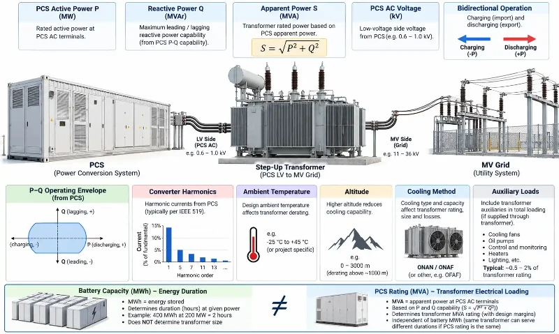
This is why a transformer cannot be selected from battery capacity alone. A 2-hour and a 4-hour BESS can use the same PCS MW rating while having very different MWh capacities, yet the transformer may see a similar peak AC power duty.
The distinction between power and energy is also important elsewhere in BESS design. The site's kW, kWh and power-versus-energy relationship should be clear before electrical equipment is sized.
Transformer Sizing Inputs That Matter
- maximum PCS active power during charge and discharge
- PCS kVA capability and P-Q operating envelope
- AC terminal voltage and allowable voltage range
- required reactive-power operation at the POI
- continuous and temporary overload duty, if specified
- ambient temperature and site altitude
- converter harmonic spectrum and expected additional losses
- transformer cooling method and temperature-rise limits
- auxiliary loads that are supplied through the same transformer path
- future expansion or operating cases that are already part of the project design basis
There is no reliable universal rule that every BESS transformer should be 10%, 20% or 25% larger than the PCS rating. A margin may be appropriate, but it should result from the required operating cases, thermal study, reactive-power duty and project contingency philosophy. Arbitrarily oversizing the transformer can increase cost, footprint and losses without solving the actual design constraint.
What Do LV and MV BESS Switchgear Actually Need to Handle?
BESS switchgear does more than provide a disconnect point. It carries normal operating current, isolates equipment for maintenance, interrupts faults and executes protection logic that determines whether a plant can remain connected to the grid.
Low-voltage and medium-voltage switchgear sit at different electrical points and therefore face different design priorities.
| Design Area | LV Switchgear | MV Switchgear |
|---|---|---|
| Typical location | Between PCS outputs and step-up transformer | Between step-up transformer, MV collector system and grid-facing equipment |
| Main continuous-duty issue | High current at relatively low voltage | Collector and feeder current at the project MV level |
| Protection focus | PCS isolation, feeder faults and thermal loading | Feeder, transformer, bus and grid-interface protection |
| Key rating checks | Continuous current, short-circuit withstand, breaker interrupting duty and busbar temperature rise | Rated voltage, continuous current, short-circuit withstand and interruption, internal-arc requirements where applicable |
| Typical associated equipment | AC breakers, busbars, isolating devices and metering | Vacuum breakers, CTs, VTs, protection relays, earthing switches and interlocks |
The switchgear voltage class varies by project. It should be selected from the actual collector-system and POI design rather than from a generic BESS voltage range.
For IEC-based metal-enclosed MV switchgear, IEC 62271-200 applies to AC metal-enclosed switchgear and controlgear above 1 kV and up to and including 52 kV. The project may also require additional IEC, IEEE, utility or national requirements depending on location and equipment scope.
Why Transformer and Switchgear Must Be Engineered Together
The transformer and switchgear may be purchased from different suppliers, but their electrical ratings are interdependent.
Transformer impedance is a clear example. It affects available short-circuit current, voltage drop and system behavior during faults. A lower or higher impedance can therefore change the duty seen by the LV and MV switchgear and can alter protection-study results. There is no single transformer-impedance percentage that is correct for every BESS project.
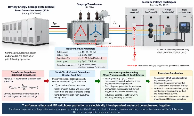
The transformer vector group and grounding arrangement also influence earth-fault behavior and relay coordination. CT connections, residual-current measurement and directional or differential protection need to reflect the actual transformer connection and system grounding.
For this reason, normal-current rating must never be used as a substitute for short-circuit withstand or interrupting capability. The switchgear must be checked against the calculated fault duty at its installation point, and the protection settings must be coordinated with the transformer, PCS, collector system and utility requirements.
The wider BESS electrical architecture should therefore be frozen far enough for all key suppliers to work from the same assumptions before equipment manufacturing is released.
Transformer Energization Also Affects the Interface
Energizing a transformer can create a transient magnetizing current that is very different from normal operating current. The magnitude depends on transformer design, switching instant, residual flux, source impedance and the energization method.
Where the BESS PCS is used as part of a controlled energization sequence, the applicable strategy may include controlled voltage ramping, switching coordination or other measures defined by the system study. These methods should be validated for the actual transformer, converter current limits and protection settings rather than copied from a generic per-unit example.
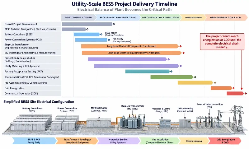
Why Electrical Balance of Plant Can Delay BESS Energization
Battery containers and PCS units do not connect themselves to the grid. Between the converter terminals and the POI sits the electrical balance of plant: transformers, switchgear, protection, metering, cabling, auxiliary supplies, communications and substation equipment.
Any one of these interfaces can stop commissioning if the equipment is incomplete or the design assumptions do not match. Typical examples include:
- the transformer impedance in the final vendor drawing differs from the value used in the short-circuit study
- switchgear CT ratios do not match the approved protection or revenue-metering design
- PCS kVA or reactive-power capability changes after the transformer has been ordered
- breaker trip voltage does not match the station DC or auxiliary supply
- cable terminations or entry locations do not match the installed equipment
- the relay study uses an obsolete single-line diagram
- the network operator has not approved the final protection settings
- late switchgear or transformer dimensional changes require civil, trench or cable-routing revisions
This is why BESS grid compatibility cannot be treated as a final commissioning check. The grid-facing requirements affect equipment specification much earlier in design.
Equipment Lead Time and Interconnection Queue Are Different Risks
A long equipment lead time is not the same problem as a grid interconnection queue. The interconnection process concerns studies, approvals and network requirements. Equipment lead time concerns engineering release, manufacturing, factory testing and delivery.
The two risks can interact, but they should be managed separately. A project can have an approved grid connection and still wait for equipment, or have all major hardware on site while protection studies and utility approvals remain incomplete.
Transformer and Switchgear Lead Times: What Developers Should Know
Transformer and switchgear procurement should be screened early because grid-equipment supply chains remain constrained in several markets. The risk, however, depends strongly on equipment class, voltage, MVA, customization, testing requirements, supplier capacity and region.
The International Energy Agency reports that procurement of large power transformers can take up to four years and that average lead times for large power transformers have almost doubled since 2021. These figures describe large grid transformers and should not be applied automatically to every BESS step-up transformer, but they show why grid-facing transformer requirements should be identified early. The findings are summarized in the IEA report Building the Future Transmission Grid.
The U.S. Department of Energy has also identified transformers, circuit breakers, substation components and power electronics among grid components facing significant supply-chain pressure. DOE notes that limited production capacity, imported materials and excessive customization have contributed to lead times of two years or more for some critical equipment. Its 2026 overview, Strengthening America's Grid Supply Chain, also highlights equipment standardization as one route to shorter production times.
Those numbers are not a universal BESS procurement schedule. A project-specific transformer or switchgear package can move faster or slower. The practical lesson is to identify long-lead electrical equipment before the construction schedule assumes that batteries are the only procurement constraint.
When Should Transformer and Switchgear Procurement Start?
Starting early does not mean placing a manufacturing order before the electrical design is understood. The objective is to develop the specification early, reserve supplier capacity where appropriate and release manufacturing when the critical interfaces are controlled.
A useful sequence is:
- Define the grid and POI requirements. Confirm connection voltage, export and import limits, reactive-power requirements, protection philosophy and utility metering needs.
- Freeze the PCS AC boundary. Confirm maximum MW, kVA, AC voltage, current limits, P-Q capability and harmonic information.
- Develop the controlled single-line diagram. Establish transformer ratio, grounding, collector architecture, switchgear arrangement and auxiliary supplies.
- Complete preliminary system studies. Short-circuit, load-flow, reactive-power and protection assumptions should be mature enough to support equipment ratings.
- Issue RFQs using one design basis. Transformer, switchgear, PCS and substation suppliers should receive compatible data and the same controlled drawing revision.
- Resolve vendor data before release for manufacture. Confirm impedance, CT/VT ratios, relay interfaces, cable terminations, auxiliary voltages and final ratings.
- Update studies with final vendor data. Do not rely on preliminary assumptions during commissioning.
This approach reduces the risk of ordering equipment too late without replacing engineering discipline with speculative procurement.
Common BESS Transformer and Switchgear Design Mistakes
Sizing the Transformer From Battery MWh
Energy capacity does not define peak AC power duty. Transformer sizing must follow the PCS kVA and the required P-Q operating cases.
Treating kW and kVA as Interchangeable
A transformer and switchgear system may need to support reactive power while the BESS is charging or discharging. Ignoring kVA can understate current and thermal duty.
Applying a Universal Transformer Oversizing Margin
A fixed percentage does not replace a loading and thermal assessment. The appropriate rating depends on operating cases, environment, harmonics, cooling and required contingency.
Using a Generic Transformer Impedance
Impedance should be selected with fault levels, voltage regulation, protection and system studies in mind. Changing it can change switchgear duty.
Selecting Breakers Only by Normal Current
Continuous current, short-circuit withstand and interrupting capability are different ratings. All must match the calculated system duty.
Leaving Protection Coordination Until Commissioning
Relay settings depend on transformer data, CT/VT ratios, system grounding, PCS fault contribution and network requirements. Waiting until site testing can turn a settings issue into a hardware problem.
Ignoring Auxiliary Power Interfaces
Breaker controls, relays, communications, cooling and station services must have defined AC and DC supplies before the plant can be commissioned.
Ordering Transformer and Switchgear as Unrelated Packages
Separate purchase orders are normal; separate design assumptions are not. The equipment must be checked against the same fault study, protection philosophy and single-line diagram.
Using Outdated Vendor Data
A project may pass preliminary studies and still fail final coordination if the equipment that was actually manufactured differs from the assumptions used in those studies.
How the Electrical Balance of Plant Fits the Wider BESS Design
Transformer and switchgear decisions sit between battery-system design and grid compliance. They affect how much of the PCS capability can reach the POI, how faults are isolated, how the plant is metered and whether the final system can be energized under the approved network conditions.
They should therefore be reviewed alongside the broader BESS component system, not after the battery block has already been finalized. A project-level design must reconcile battery limits, PCS capability, electrical balance of plant, controls, protection and the grid connection as one system.
Frequently Asked Questions
What is a BESS transformer?
A BESS transformer connects the PCS AC side to the required collection or grid voltage. Its design must reflect the PCS power and voltage range, bidirectional operation, reactive-power duty, harmonics, thermal conditions, grounding and system-protection requirements.
Does BESS MWh determine transformer size?
No. Battery MWh describes stored energy. Transformer size is driven primarily by the PCS apparent-power duty, voltage, P-Q operating envelope, thermal conditions, harmonics and other project-specific loads and requirements.
What is the difference between LV and MV BESS switchgear?
LV switchgear commonly collects and isolates PCS outputs before the step-up transformer, where current can be high. MV switchgear operates on the collector or grid-facing side and must satisfy the project's voltage, continuous-current, fault-interruption, protection and utility-interface requirements.
Why must a BESS transformer and switchgear be coordinated?
Transformer impedance, vector group and grounding affect short-circuit behavior and protection. Those values directly influence breaker ratings, CT/VT arrangements and relay settings, so transformer and switchgear specifications cannot be finalized independently.
Why can transformer procurement delay a BESS project?
Transformer delivery depends on rating, voltage, customization, testing, supplier capacity and region. Large grid transformers in particular have experienced long procurement periods. A BESS project should therefore identify its transformer class and supplier schedule early instead of assuming the battery container is the longest-lead item.
When should a BESS transformer RFQ be issued?
The RFQ should begin once the project has a sufficiently controlled PCS AC boundary, grid voltage, operating cases, preliminary SLD, transformer requirements and protection basis. Manufacturing release should wait until critical vendor and interface data are resolved.
Conclusion: Keep the Electrical Interface Off the Critical Path
A BESS transformer and switchgear lineup should not be treated as secondary hardware between the battery and the grid. Together with protection, metering, auxiliary power and cabling, they form the electrical path that allows the project to energize.
The most reliable way to keep that path from delaying COD is to define the PCS and grid interfaces early, size the transformer from real kVA and operating cases rather than MWh, coordinate transformer and switchgear ratings through common system studies, control the single-line diagram across suppliers and begin long-lead procurement before the construction schedule becomes dependent on it.
Battery containers may represent the largest share of visible storage equipment, but project readiness is decided by the complete electrical system. If the transformer, switchgear, protection and POI interfaces are not ready, the battery cannot deliver its value to the grid.