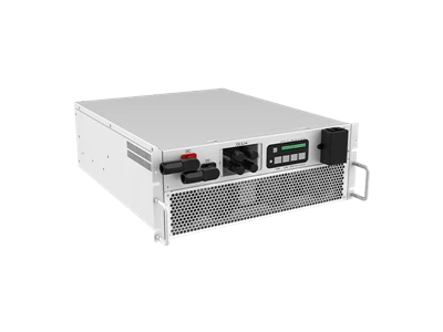
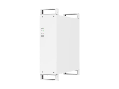
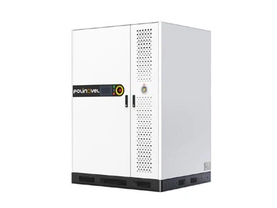
30kW–500kW Microgrid Hybrid Inverter
The 30kW–500kW Microgrid Hybrid Inverter is a compatible accessory option for Polinovel battery energy storage projects, designed for solar-plus-storage, off-grid power, diesel hybrid, and weak-grid applications. It supports coordinated operation across PV input, battery storage, grid connection, diesel generator operation, and backup power supply.
With integrated MPPT, transformer, STS, and maintenance bypass functions, this microgrid hybrid inverter helps simplify system configuration and reduce external component matching. It is suitable for remote mines, islands, farms, villages, C&I microgrids, and other projects where stable power conversion and flexible energy dispatch are required.

Optimized for Your Energy Needs
Integrated Hybrid Power Design
This microgrid hybrid inverter integrates MPPT, transformer, STS, and maintenance bypass functions to simplify PV + BESS + diesel hybrid system configuration. It helps reduce separate component matching and supports more efficient project deployment for remote and weak-grid energy applications.
The isolation transformer separates the battery DC side from the AC distribution side, and the maintenance bypass allows the load to stay energised from the grid while the inverter is serviced - a practical requirement on sites where a shutdown window is hard to obtain.
Flexible PV and Battery Configuration
With adaptive MPPT step-up/down technology, the inverter supports flexible PV capacity matching for different solar-plus-storage projects. It can be configured according to PV capacity, battery voltage range, load demand, and site conditions, making it suitable for various microgrid applications.
The 250–1000 V MPPT window accepts short strings on constrained roofs as well as full-length strings on ground-mounted arrays. Depending on model, 1 to 10 MPPT modules are available, and maximum PV power reaches up to 825 kW on the 500 kW unit - allowing PV oversizing where irradiance is seasonal or where the array feeds both the load and the high-voltage battery during the same daylight hours.
Reliable Off-Grid Microgrid Operation
The inverter supports 100% unbalanced loads and parallel connection of multiple units, helping improve system stability in off-grid and weak-grid environments. It is suitable for applications such as mining sites, islands, nomadic farms, and villages without stable electricity access.
Full unbalanced-load capability matters wherever single-phase feeders are distributed unevenly across three phases, which is the normal condition in village networks and camp distribution boards. Off-grid overload capacity is 110% continuous and 120% for one minute, giving headroom for motor starting on pumps, compressors and conveyors.
Diesel Generator Fuel Optimization
For solar-diesel-battery microgrids, DG load rate control helps coordinate generator output with PV generation, battery storage, and load demand. This can improve fuel economy and reduce unnecessary diesel generator runtime in hybrid power projects.
Holding the generator above its minimum recommended load rate avoids wet stacking and the maintenance cost that follows it, while the battery absorbs short load peaks that would otherwise force a second genset to start.
Specification
|
AC(on-grid)
|
||||||
|
Max. output power (kW)
|
33
|
55
|
110
|
165
|
275
|
550
|
|
Rated output power
|
30kW
|
50kW
|
100kW
|
150kW
|
250kW
|
500kW
|
|
Rated voltage
|
400V
|
|||||
|
Voltage range
|
320~460V
|
|||||
|
Rated current
|
43A
|
72A
|
144A
|
216A
|
361A
|
722A
|
|
Rated frequency
|
50/60Hz
|
|||||
|
Frequency range
|
45~55/55~65Hz
|
|||||
|
THDi
|
<3%
|
|||||
|
Power factor
|
1leading-1lagging(settable)
|
|||||
|
Grid type
|
3W+N+PE
|
|||||
|
AC(off-grid)
|
||||||
|
Max. output power
|
33kW
|
55kW
|
110kW
|
165kW
|
275kW
|
550kW
|
|
Rated power
|
30kW
|
50kW
|
100kW
|
150kW
|
250kW
|
500kW
|
|
Rated voltage
|
400V
|
|||||
|
Rated current
|
43A
|
72A
|
144A
|
216A
|
361A
|
722A
|
|
THDu
|
≤1% linear; or≤5% nonlinear
|
|||||
|
Rated frequency
|
50/60Hz
|
|||||
|
Overload capacity
|
110% long-term, 120% 1min
|
|||||
| PV input | ||||||
|
Max. PV input voltage
|
1000V
|
|||||
|
Max. PV power (kW)
|
82.5kW
|
82.5kW
|
165/247.5kW
|
165/247.5/330kW
|
330/412.5kW
|
660/742.5/825kW
|
|
MPPT module quantity
|
1
|
1
|
2/3
|
2/3/4
|
4/5
|
8/9/10
|
|
MPPT voltage range
|
250~1000V
|
|||||
|
Battery
|
||||||
|
Battery voltage range
|
250~850V
|
320~850V
|
420~950V
|
420~950V
|
420~950V
|
500~950V
|
|
Max. charging power
|
33kW
|
55kW
|
110kW
|
165kW
|
275kW
|
550kW
|
|
General data
|
||||||
|
Dimension W*D*H
|
800*800*1900mm
|
800*800*1900mm
|
1,200*800*2,050mm
|
1,200*800*2,050mm
|
(600*720*2,050)*1+
1,200*800*2,050mm
|
(600*720*2,050)*2+
1,600*1,050*2,050mm
|
|
Weight (kg)
|
620
|
720
|
1,120/1,150
|
1,250/1,280/1,310
|
1,950/1,980
|
3,205/3,235/3,265
|
|
Operation temperature
|
30 ~ 55℃
|
|||||
|
Relative humidity
|
0 ~95% non-condensing
|
|||||
|
Ingress protection
|
IP20
|
|||||
|
Noise emission (dB)
|
<70
|
|||||
|
Operating altitude (m)
|
>3,000 Derating
|
|||||
|
Cooling
|
Air Cooling
|
|||||
|
Display and communication
|
||||||
|
Display
|
LCD touch-screen
|
|||||
|
BMS communication
|
RS485, CAN
|
|||||
|
EMS communication
|
RS485, TCP/IP
|
|||||
|
Certificates
|
EN 62109-1/-2, EN 62477-1, EN 61000-6-2/-6-4, NRS 097-2-1:2024, ASGC
|
|||||
Available Models
Six power ratings share the same 400 V three-phase architecture.
| Rated power | Max. output | AC rated current | Max. PV power | MPPT modules | Battery voltage | Typical application |
|---|---|---|---|---|---|---|
| 30 kW | 33 kW | 43 A | 82.5 kW | 1 | 250–850 V | Telecom site, farm, small village grid |
| 50 kW | 55 kW | 72 A | 82.5 kW | 1 | 320–850 V | Lodge, clinic, pumping station |
| 100 kW | 110 kW | 144 A | 165 / 247.5 kW | 2 / 3 | 420–950 V | Workshop, cold storage, weak-grid factory |
| 150 kW | 165 kW | 216 A | 165 / 247.5 / 330 kW | 2 / 3 / 4 | 420–950 V | Hotel, processing plant, island microgrid |
| 250 kW | 275 kW | 361 A | 330 / 412.5 kW | 4 / 5 | 420–950 V | Mining camp, port facility |
| 500 kW | 550 kW | 722 A | 660 / 742.5 / 825 kW | 8 / 9 / 10 | 500–950 V | Off-grid mining site, C&I microgrid |
System Topology: How PV, Battery, Grid and Diesel Generator Work Together
Single-line arrangement of a typical PV + battery + diesel microgrid built around one inverter cabinet.

PV array and battery share the DC bus, so surplus solar charges the battery without an intermediate AC conversion stage. Grid and diesel generator connect on the AC side; the internal static transfer switch decides which source supports the load, and the maintenance bypass keeps the load energised from the grid during servicing. Where the storage side is supplied as a complete enclosure rather than as racks, the same topology applies to an outdoor cabinet BESS or a containerized BESS.
Working Modes
Choose the plan that suits you best.
Self-consumption
PV supplies the load first; surplus charges the battery instead of being exported. The grid covers any shortfall.
Peak shaving
The battery discharges above a set import threshold so the metered demand stays flat. Peak shaving is normally the first payback mechanism on a C&I connection.
Time-of-use shifting
Charging is scheduled in low-tariff hours and discharge in high-tariff hours.
Backup power
The static transfer switch isolates the utility connection and the inverter re-establishes the 400 V bus from the battery and PV.
Off-grid operation
The inverter forms the grid itself, holding 400 V / 50–60 Hz with THDu ≤1% on linear load and ≤5% on nonlinear load.
Diesel hybrid
DG load rate control keeps the generator inside its efficient loading band; PV and battery take the rest and shorten runtime.
PV priority
Solar serves load and charging before any other source is called, which is the default dispatch on fuel-constrained sites.
Maintenance bypass
The load is transferred to the grid through the internal bypass so the inverter can be isolated without a site blackout.
Applications: Site Conditions That Decide Inverter Selection
| Site condition | What makes it electrically difficult | Governing parameter on this unit |
|---|---|---|
| No utility connection | The inverter has to form the AC bus itself and hold voltage and frequency through every load step, with no grid reference to follow. | 400 V / 50–60 Hz grid-forming output; THDu ≤1% linear, ≤5% nonlinear |
| Diesel generator on site | The genset must stay above its minimum load rate to avoid wet stacking, while short peaks must not force a second unit to start. | DG load rate control; 110% long-term and 120% for 1 min overload |
| Unbalanced single-phase feeders | Phase currents differ substantially, which forces a conventional three-phase inverter to derate to the worst phase. | 100% unbalanced load capacity |
| Direct-on-line motor starting | Pumps, compressors, conveyors and crushers draw several times rated current for a few seconds at start. | 120% for 1 min; parallel connection of multiple units |
| Weak or unstable utility | Voltage and frequency wander outside nominal, and dips occur often enough to interrupt production. | 320–460 V and 45–55 / 55–65 Hz operating window; static transfer switch |
| Seasonal or oversized PV array | The array is deliberately larger than the AC rating so that winter or monsoon yield still covers the load. | Max. PV up to 825 kW against 500 kW AC; 250–1000 V MPPT window, 1–10 MPPT modules |
| Wide ambient range or high altitude | Cold starts, high daytime temperature and thin air all reduce the continuous rating a cabinet can hold. | -30 to 55 ℃, air cooling, derating above 3,000 m |
| Capacity added in stages | Load grows after commissioning and the original cabinet is no longer sufficient on its own. | Parallel operation of multiple units on the same 400 V bus |
| Service without a blackout window | Continuous-process or critical sites cannot be de-energised to work on the conversion equipment. | Integrated maintenance bypass; load stays on the grid during isolation |
FAQ
Q: What is the difference between a microgrid hybrid inverter and a PCS?
A: A PCS converts between the battery DC side and the AC side only. A microgrid hybrid inverter adds PV MPPT inputs and the transfer switching that lets the system run on-grid and off-grid, so one cabinet replaces a PV inverter, a PCS and an external transfer switch. The role of the converter on its own is explained under power conversion system.
Q: Can the inverter work without a utility grid connection?
A: Yes. In off-grid operation it forms the AC bus itself at 400 V and 50/60 Hz, with output distortion of ≤1% on linear load and ≤5% on nonlinear load. No grid reference is required.
Q: How much PV can be connected to each model?
A: Maximum PV power runs from 82.5 kW on the 30 kW and 50 kW models up to 825 kW on the 500 kW model, using 1 to 10 MPPT modules depending on configuration. Maximum PV input voltage is 1000 V and the MPPT tracking window is 250–1000 V.
Q: What battery voltage does the inverter accept?
A: 250–850 V on the 30 kW unit, 320–850 V on the 50 kW unit, 420–950 V on the 100–250 kW units and 500–950 V on the 500 kW unit. The battery bank must be selected within the range of the specific model.
Q: Can several units be paralleled?
A: Yes. Parallel connection of multiple units is supported, which is the normal approach when the site peak load exceeds a single cabinet or when the microgrid is expected to grow in stages.
Q: Does it support unbalanced single-phase loads?
A: The inverter supports 100% unbalanced load. This is a requirement on village networks and camp distribution boards where single-phase circuits are not evenly split across the three phases.
Q: How does it reduce diesel consumption?
A: DG load rate control keeps the generator within its efficient loading band while PV and battery supply the remainder, and the battery absorbs short peaks that would otherwise require a second genset. Runtime falls, and so does the maintenance caused by prolonged light loading.
Q: What is the operating temperature range?
A: -30 to 55 ℃, with 0–95% non-condensing humidity, IP20 protection, air cooling, and derating above 3,000 m altitude. Battery limits are usually narrower, so the enclosure and thermal design are checked against the lithium battery temperature range as well.
Q: What communication interfaces are available?
A: RS485 and CAN for BMS communication, RS485 and TCP/IP for EMS communication, plus a local LCD touch-screen.
Q: Which grid codes does the inverter comply with?
A: EN 62109-1/-2, EN 62477-1, EN 61000-6-2/-6-4, NRS 097-2-1:2024 for South Africa, and ASGC. Additional national certification can be discussed per project.

Send Your Load Profile for a Microgrid Configuration
The more of the electrical picture we have, the closer the first proposal will be.
Hot Tags: 30kw–500kw microgrid hybrid inverter, China 30kw–500kw microgrid hybrid inverter manufacturers, suppliers, factory