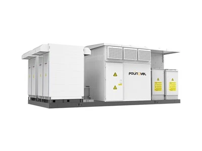
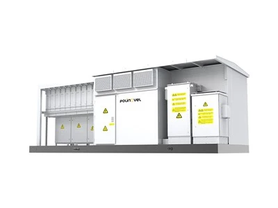
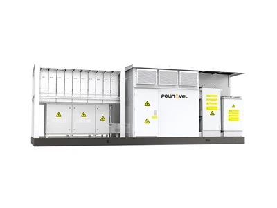
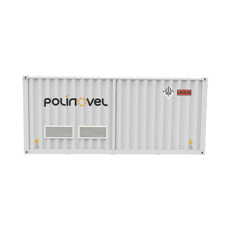
PCS & Transformer Integrated Container
The PCS & Transformer Integrated Container is a high-power centralized power block designed for utility-scale energy storage systems that require efficient PCS conversion and medium-voltage grid connection.
It integrates PCS conversion and step-up transformer functionality into one electrical unit, providing a compact and efficient interface between battery systems and the grid. Compared with separate PCS and transformer installations, this solution reduces on-site electrical matching work, simplifies system layout, and improves overall integration efficiency for large-scale BESS projects.

Key features of our energy storage containers
PCS and Transformer Integrated Architecture
The system integrates PCS conversion and step-up transformer into one electrical unit, replacing the traditional separated PCS and transformer configuration in BESS projects.
High-Power Centralized Energy Conversion Unit
Designed as a 6900kVA power block, the system provides centralized conversion for large battery energy storage plants, supporting stable high-capacity power transmission.
Unified Electrical Architecture Design
By combining PCS, transformer, protection, and control functions into one containerized unit, the system reduces system fragmentation and improves overall electrical structure consistency.
Flexible Battery System Interface
Supports 2 / 4 battery group access with independent charge and discharge control, allowing flexible configuration of centralized battery energy storage systems.
Specification
| DC Parameters | ||
| Max. DC Voltage | 1500V | |
| Max. DC Current | 3872A | 4490A |
| Battery Group Voltage Range | 1000–1500V | |
| Number of Connectable Battery Groups | 2 | |
| AC Parameters (Grid-connected) | ||
| Rated AC Power | 3450kW | 4000kW |
| Rated Grid Voltage | 10–35kV | |
| Rated Grid Frequency | 50/60Hz | |
| THD at Rated Power | <3% | |
| Power Factor Adjustable Range | -1~+1 | |
| System Features | ||
| Isolation Method | Dry-type / Oil-immersed Transformer | |
| Max. System Efficiency | 98% | |
| Protection Rating | IP65 (Converter) / IP54 (Others) | |
| Operating Temperature Range | -40~+60℃ (>45℃ Derating) | |
| Allowable Humidity Range | 0–100% (Non-condensing) | |
| Max. Operating Altitude | 5000m | |
| Cooling Method | Intelligent Air Cooling (Converter) | |
| Communication Interface | RS485 / CAN / Ethernet | |
| Mechanical Parameters | ||
| Dimensions | 7000×3000×2896mm (Dry-type) / 6058×2438×2896mm (Oil-immersed) | |
| Weight | 14500kg (Dry-type) / 15000kg (Oil-immersed) | |
How much storage one power block carries
Energy per block follows from the AC rating and the discharge duration the project is built for.
| Configuration | 2-hour system | 4-hour system | Blocks per 100 MW |
|---|---|---|---|
| 3450 kW | ≈ 6.9 MWh | ≈ 13.8 MWh | 29 |
| 4000 kW | ≈ 8.0 MWh | ≈ 16.0 MWh | 25 |
Two battery groups per block
The specification table lists two DC inputs across the 1000–1500 V window with independent charge and discharge control, so the number of battery containers per block is set by how the DC side of those containers is grouped and paralleled.
Current, not power, sizes the DC cabling
Because the same output is delivered at any point in the voltage window, the worst case for cable, fuse and terminal selection is the bottom of the window - which is where the 3872 A and 4490 A totals apply, roughly 1940 A and 2250 A per input.
What connects at each face of the container
Battery side
Two DC inputs across a 1000–1500 V window, carrying a combined 3872 A or 4490 A depending on configuration, with independent charge and discharge control per group.
Grid side
A single medium-voltage connection at 10–35 kV, 50/60 Hz, with THD below 3% at rated power and power factor adjustable from -1 to +1.
Control side
RS485, CAN and Ethernet for the link to the BMS and the plant control layer. Point lists are matched to the battery system on each project.
Cooling
Intelligent air cooling on the converter; the wider cooling system selection for the plant is made alongside the battery containers.
Site envelope
-40 to +60℃ with derating above 45℃, 0–100% non-condensing humidity, altitude to 5000 m. Hot or high sites should be declared at enquiry.
Protection
IP65 on the converter section and IP54 elsewhere, with electrical protection and system coordination handled inside the unit.
The transformer and switchgear data that closes the design
| Item | What it determines |
|---|---|
| Transformer vector group | Phase displacement between LV and MV windings, and how the neutral is treated on each side. |
| Impedance voltage (uk%) | Fault current contributed to the network, and voltage drop across the transformer at full load. |
| Tap range | How far the block can hold its output as network voltage moves across the day. |
| Cooling class | Continuous rating against forced-cooled rating - AN/AF for the dry-type build, ONAN for the oil-immersed build. |
| Neutral earthing | Earth-fault current level and the protection scheme that has to detect it. |
| MV switchgear configuration | Busbar rating, short-circuit withstand and incomer/feeder arrangement, to IEC 62271-200. |
| Protection functions | Overcurrent, earth fault and differential settings, coordinated with the upstream collection network. |
Fixed by the product
Output at 10–35 kV, 50/60 Hz, with THD below 3% at rated power and power factor adjustable from -1 to +1. Isolation is by dry-type or oil-immersed step-up transformer.
Fixed by the network
Fault level at the point of connection, earthing philosophy and the protection grading of the collection network. These decide the switchgear rating and the transformer impedance, so they are worth raising before the build is frozen.
Which standards apply, and where
| Scope | Standards commonly required |
|---|---|
| North America - converter and interconnection | UL 1741 with the supplement matching the adopted IEEE 1547 edition; IEEE 2800 where the plant connects at transmission level. |
| North America - system and site | UL 9540 at system level, with NFPA 855 and NEC Article 706 governing the installation. |
| Europe - converter and grid connection | CE marking, IEC 62477-1 for power-electronics safety, and EN 50549 or the national code derived from the RfG network code. |
| Equipment standards | IEC 60076 for the step-up transformer (or IEEE C57.12.00 where a US-standard transformer is specified), IEC 62271-200 for the MV switchgear, IEC 61000 for EMC. |
| Oil-immersed builds | Containment sized to local environmental rules; IEEE 980 is the usual reference for substation oil spill control. |
Where this block sits among the PCS containers
This container is the centralized option: two battery groups feeding one converter stage, at 3450 kW or 4000 kW per block.
Where a plant needs more groups behind a single higher-rated block, the integrated PCS and step-up transformer configuration takes
2 or 4 groups at 6900 kVA. Where cluster-level control matters more than block density, the string PCS turnkey station manages
8 or 16 groups on independent converter paths. All three sit in the modular PCS container range.
FAQ
Q: How much DC current does the block draw at full power?
A: It depends on where the pack sits in the 1000–1500 V window. Using the 98% system efficiency figure, rated output needs roughly 3520 A at 1000 V for the 3450 kW build and about 4080 A for the 4000 kW build, falling to roughly 2350 A and 2720 A at 1500 V. The stated maxima are 3872 A and 4490 A in total, shared across the two DC inputs.
Q: How much storage capacity does one container support?
A: Indicatively 6.9 MWh at 3450 kW and 8.0 MWh at 4000 kW for a two-hour system, doubling for a four-hour system, before auxiliary consumption and depth of discharge are applied. Final capacity is set against the battery system selected.
Q: Which transformer option keeps to a standard container footprint?
A: The oil-immersed build, at 6058 × 2438 mm in plan. The dry-type build measures 7000 × 3000 mm, which exceeds standard container width and is transported as an out-of-gauge load.
Q: How many battery groups connect to one container?
A: Two DC inputs across a 1000–1500 V range, each with independent charge and discharge control, at up to 3872 A or 4490 A depending on the configuration selected.
Q: What happens above 45℃ or at high altitude?
A: The unit operates from -40 to +60℃ with derating above 45℃, and up to 5000 m. Sites that are consistently hot, high or corrosive should be raised at the enquiry stage so the configuration accounts for it.
Q: What information is needed for a configuration proposal?
A: Required MW and MWh, battery DC voltage range and group arrangement, grid voltage and frequency, transformer preference, ambient temperature and altitude, installation country and grid code, and the target delivery date.

Configure a PCS & Transformer Integrated Container
Send the battery DC voltage range, required MW and MWh, grid voltage and site conditions, and we will return a matched block configuration with a single-line diagram and datasheet.
Hot Tags: PCS & Transformer Integrated Container, PCS-MV skid, bidirectional PCS, step-up transformer for BESS, MV switchgear, 1500V PCS, utility-scale BESS power block, medium voltage grid connection, energy storage step-up substation