


BESS for electric tugboat charging can store energy between berth visits and supply charging power above the port's available grid capacity. The shore-side battery energy storage system needs enough discharge power for the charging peak, enough usable energy for the session and enough time to recharge before the next arrival.
The shore battery is separate from the tug's propulsion battery. It can bridge a short power peak, but it cannot compensate indefinitely for a port connection that supplies less energy than the fleet consumes. Tug dispatch patterns, vessel charging acceptance and other port loads determine whether a battery-buffered installation can sustain daily operations.
Recent Vessel Projects Show Two Different Charging Needs
In a November 17, 2026 report on Curtin Maritime's first electric tug, American Journal of Transportation described Tuuli C undergoing sea trials as the first vessel in an eight-tug program. Curtin reported that existing shore power could support overnight charging, while fast-charging barges with battery storage were being developed for the expanding fleet.
A different example appears in Environment+Energy Leader's September 10 report on mobile vessel charging. Tidal Transit deployed a Fellten CQ450 shore-side system, rated at 450 kWh with charging power up to 240 kW, to support overnight charging of e-Ginny, an electric crew transfer vessel. Its overnight charging task differs from a tug's short turnaround between ship-assist assignments.
A tug that remains at its base overnight may have a substantially different charging requirement from one that must return to ship-assist work after a brief stop. The usable charging window determines how much power is necessary.
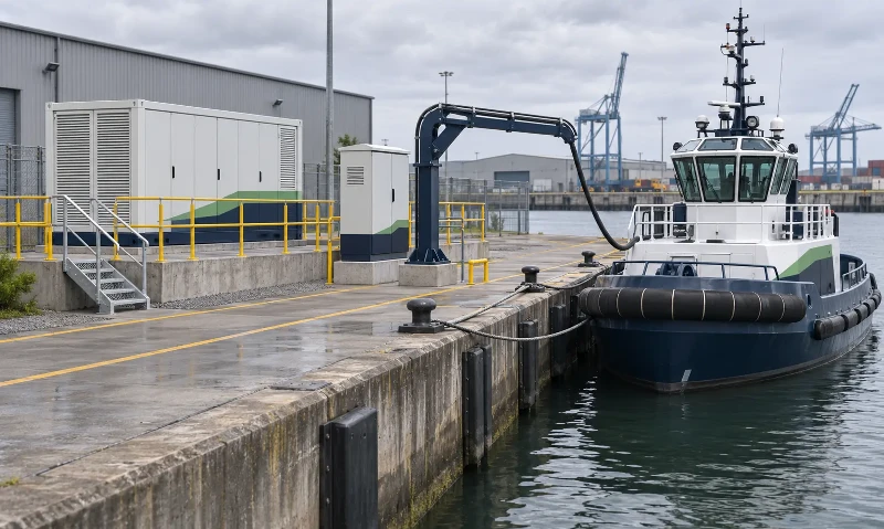
Tugboat Charging Power Follows the Berth Window
Charging demand starts with the energy the vessel must recover before its next assignment. Bollard pull and propulsion motor ratings do not directly establish the shore charger rating. The relevant operating information is the energy consumed between visits, the required departure state of charge and the time during which the tug can actually accept charge.
Time alongside includes mooring, connecting the charging cable, completing interface checks and disconnecting before departure. Those activities reduce the powered charging window. Battery temperature, state of charge and the vessel's charging controls can also reduce accepted power below the charger's nameplate rating.
| Operating Pattern | Charging Requirement | Effect on Shore-Side Storage |
|---|---|---|
| Overnight at a home berth | Recover the required energy over a long connected period. | Grid-only charging may be sufficient if the available connection and vessel interface can deliver that energy in time. |
| Short stops between tug assignments | Deliver the required energy within a limited powered window. | A battery buffer may supply the power above the port's available grid headroom. |
| Several tugs returning together | Charge multiple vessels against overlapping departure deadlines. | Combined demand and the energy available in storage determine whether charging can continue without delaying a departure. |
For example, adding energy for another ship-assist assignment may be possible during a short visit, while restoring a heavily depleted propulsion battery could require a longer stay. An average daily energy figure alone misses that operational difference.
Size the Shore-Side BESS Against the Charging Power Deficit
The relevant grid limit is the active power remaining after other port loads, not the transformer nameplate. Cargo-handling equipment, buildings and other charging installations may share the same connection. Transformer capacity in kVA also cannot be treated as an equal amount of available kW without considering power factor and operating limits.
For an AC-coupled installation, the instantaneous power gap at the common AC bus is:
Required BESS AC discharge power = charger AC input demand − available grid headroom, whenever charger demand exceeds that headroom.
The energy requirement is the accumulated power deficit over the charging session. For a changing load, it is the sum of each positive deficit multiplied by its duration. A vessel's onboard battery capacity is not the same as the required shore-side BESS capacity.
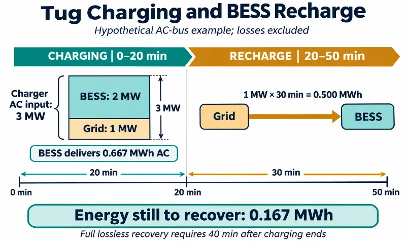
Illustrative calculation, not a customer project: assume one charging installation draws a constant 3 MW at its AC input for 20 minutes. The grid can supply 1 MW to that charging bus throughout the session. All values below are at the AC bus and exclude losses, auxiliary consumption and operating reserves.
| Quantity | Calculation | Illustrative Result |
|---|---|---|
| Charger AC input energy | 3 MW × 20/60 hours | 1.000 MWh |
| Grid contribution during charging | 1 MW × 20/60 hours | 0.333 MWh |
| BESS AC discharge power | 3 MW − 1 MW | 2 MW |
| BESS energy delivered to the AC bus | 2 MW × 20/60 hours | 0.667 MWh |
The PCS must support the required 2 MW discharge for the full session under the specified site conditions. The battery must also sustain that discharge rate; an adequate PCS rating does not establish the battery's continuous output capability.
The 0.667 MWh figure is delivered AC energy, not battery nameplate capacity or energy stored in the tug. Battery sizing also includes the permitted SOC range, discharge-path efficiency, end-of-life capacity, temperature-related limits, auxiliary demand and the reserve retained for the next vessel. Charger losses further reduce the energy reaching the vessel battery.
Check Recharge Time Before the Next Tug Arrives
After the example session, the shore battery has supplied approximately 0.667 MWh to the AC bus. If 1 MW remains available for replenishment, and the BESS can accept that power, replacing the energy takes at least 40 minutes in the same lossless calculation. Actual replenishment takes longer once charging losses and auxiliary consumption are included.
If the next identical session begins only 30 minutes after the previous one ends, the grid can provide at most 0.500 MWh during that gap. The resulting shortfall is approximately 0.167 MWh per cycle before losses. A larger battery can absorb several such deficits, but its SOC will continue to fall if the pattern repeats without a longer recovery period.
Repeated tug arrivals therefore need a full operating-day energy balance, including late returns, overlapping sessions and periods when cargo activity reduces spare grid power. Increasing the charger rating or adding connectors does not resolve a recurring energy shortage. More replenishment time, additional supply or a different charging schedule is needed.
Coordinate Berth Charging with Tug Dispatch
Charging priority follows the next assignment and the energy needed to complete it. A tug due to leave first may need priority over another vessel that can remain alongside. The required departure reserve comes from the vessel operator's operating plan and onboard battery limits; it is not a universal SOC percentage.
The shore energy management system coordinates charger demand with measured port import, available BESS power and stored energy. It also needs an updated charging request from each vessel or charging controller. Unexpected early dispatch can shorten a session; a delayed return can bring two vessels onto the same charging bus together.
When cargo equipment raises port demand, the controller can increase battery support within its limits or reduce charging power according to the agreed operating priorities. A reduction in charging power changes the achievable departure energy, so the fleet operator needs that information while there is still time to adjust the assignment.
Loss of communications requires a defined fallback, such as a reduced charging limit or controlled stop. The EMS coordinates operation; fast electrical protection and emergency shutdown remain functions of the relevant protective equipment and charging interface.
Separate Shore Storage from the Marine Charging Interface
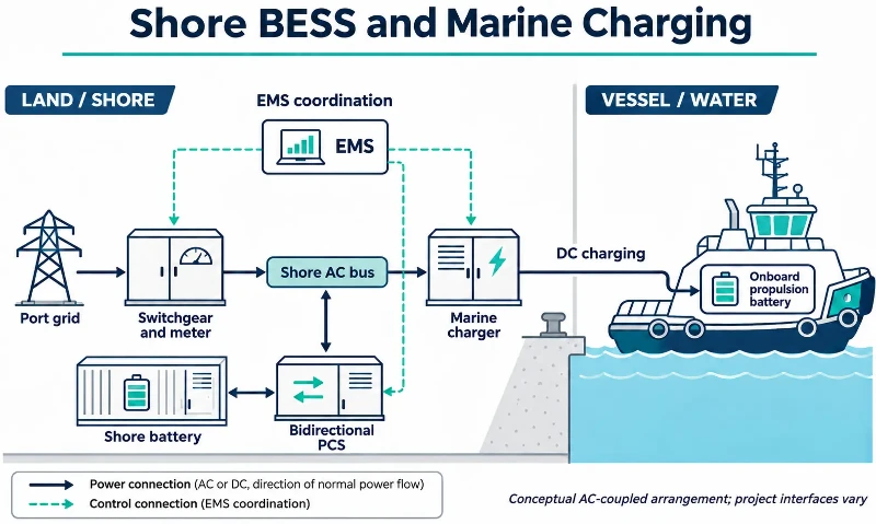
In an AC-coupled arrangement, the battery and bidirectional PCS connect to the shore AC bus. The vessel charger converts that AC supply to the DC voltage and current accepted by the onboard battery. Switchgear, transformers where needed, metering and protection connect these stages.
A DC-coupled design can connect storage and charging through an engineered DC bus and suitable conversion equipment. It changes the conversion path but still requires coordinated voltage ranges, fault protection, isolation where required and communication with the vessel. A battery DC output cannot simply be connected to the propulsion battery.
Marine charging also includes cable handling across a moving berth, connector retention, interlocks, emergency release or shutdown arrangements and coordination with the vessel's charging controls. Tide, vessel movement and personnel access affect the physical connection. A connector used for road vehicles does not establish compatibility with a tugboat.
Similarly, a grid-connected BESS does not automatically keep charging during a utility outage. Islanded operation needs the appropriate PCS controls, separation from the utility, protection and a coordinated transition. Otherwise, an outage may stop charging even when the battery still contains energy.
Match Fixed, Mobile or Floating Storage to the Berth
Fixed shore-side storage can serve recurring charging demand at a permanent base. Its location affects cable length, electrical losses, access for maintenance and separation from vessel movements. Flood exposure, salt contamination and the battery system's environmental limits matter alongside electrical capacity.
Mobile storage can provide an interim source while permanent port electrical works proceed, or support successive prepared berths. Relocation also takes the battery away from service and requires safe isolation, transport and reconnection. If the unit must leave to recharge, that absence belongs in the vessel charging schedule.
A floating charging platform can bring the charging equipment closer to vessels where shore layout is restrictive. It introduces mooring, stability, motion, access and marine approval requirements in addition to the electrical design. A containerized or trailer-mounted land BESS is not automatically suitable for installation on a barge.
Polinovel's containerized and mobile BESS ranges provide storage options for land-based energy projects. At a tug berth, the storage package, marine charger and vessel connection have separate specifications. The project electrical design coordinates their voltage ranges, controls and protection.
Evaluate Charging Cost Against Delivered Energy and Vessel Availability
The economic comparison is between ways of delivering the required vessel energy on time: direct grid charging, a larger connection, a battery-buffered installation or a combination. Where overnight charging already meets the operating schedule, storage needs a separate operational or tariff benefit to justify its cost.
Battery-buffered charging adds conversion losses, auxiliary consumption, maintenance and battery wear. Its value can include supporting a short turnaround, limiting billed demand where the local tariff allows, or enabling an interim charging operation before a grid upgrade. Those benefits depend on the port's actual tariff and tug utilization; they do not establish a standard payback period.
Cost per delivered MWh should use energy measured at a consistent boundary, such as the vessel charging connection, rather than battery nameplate capacity. The comparison also includes the consequence of an unavailable berth, charger or battery section. A single high-power charger may meet the energy calculation but leave the fleet without a charging path during maintenance.
A workable installation supplies the required energy within the real berth window, retains the agreed operating reserve and recovers before the next arrival. Those conditions, together with a compatible marine charging interface, determine whether shore-side BESS can support the tug fleet's schedule.