


A commercial solar battery storage project is not ready for equipment procurement simply because the solar inverter and battery cabinet have suitable power ratings. The project team must also confirm how the photovoltaic (PV) system and battery energy storage system (BESS) connect, exchange control signals, comply with grid-export conditions and operate together under changing site loads.
This checklist is for commercial solar-plus-storage projects being designed or prepared for deployment. It covers the documents, interface decisions, safety evidence and acceptance tests that an owner, EPC contractor and equipment suppliers should agree on before the project advances. It is not a substitute for a site-specific electrical design or approval from the relevant utility and authorities.
What Must Be Checked Before a Commercial Solar + BESS Project Proceeds?
Before releasing equipment for purchase or installation, the project team should be able to answer five questions: Is the design basis complete? Are the PV, PCS and grid interfaces defined? Does the control scheme cover charging and export limits? Is the safety and permitting evidence applicable to the proposed configuration? And is there an agreed plan to test the two systems together?
| Review area | Evidence needed before release | What remains unresolved without it |
|---|---|---|
| Design basis | PV and load data, operating objectives, grid conditions | Unconfirmed duty and design assumptions |
| Electrical interfaces | Single-line diagram, equipment ratings, metering and protection design | Connection or protection conflicts |
| Operating controls | Control narrative, signal list, export and charging rules | Conflicting dispatch or incorrect grid exchange |
| Safety and approvals | Applicable product evidence, site layout, authority requirements | Approval gaps and possible layout changes |
| Delivery and testing | Responsibility matrix, test plan, acceptance criteria | Missing scope or unverified combined operation |
A project may have open items during preliminary design. The important distinction is whether those items are recorded, assigned to an owner and resolved before the decision they affect. For example, an incomplete communications map may not stop an initial budget request, but it should not be treated as proof of PV inverter and BESS controller compatibility.

Establish the PV + BESS Design Basis
The design basis should describe the actual site, not a generic solar-plus-storage configuration. For an existing PV installation, start with as-built drawings and the installed inverter models. For a new project, use the proposed design and keep unapproved assumptions visible until they are confirmed.
| Design input | Source document | Review question |
|---|---|---|
| PV capacity and configuration | Array layout, DC and AC ratings, inverter schedule | Which PV equipment is installed or specified, and at which connection points? |
| PV production | Historical generation data or supported generation forecast | When is surplus generation available, and what data resolution is usable? |
| Facility demand | Interval meter data and operating schedule | How does the site load vary while PV and the battery are operating? |
| Existing distribution | Current single-line diagram and equipment records | Where can the BESS connect, and what needs engineering verification? |
| Utility connection | Interconnection agreement or utility requirements | What import, export and protection conditions apply at the utility boundary? |
| Charging permissions | Project operating requirements and applicable program terms | May the battery charge from PV, the grid, or both? |
| Operating modes | Owner's functional specification | Is the system grid-connected only, or is approved backup operation required? |
| Site constraints | Layout, environmental and access information | What physical or operating restrictions affect equipment placement? |
The purpose of this review is to agree on the starting conditions for integration. Detailed battery sizing and equipment selection are separate decisions; they should not obscure missing site data or undefined operating rules.
The project must also identify its actual coupling arrangement. An AC-coupled design may connect the PV inverter and battery PCS on separate branches of a site AC network. A DC-coupled arrangement can use a shared DC-side conversion architecture, subject to the selected equipment. The interface documents, not a general claim about efficiency, should decide which arrangement is workable. A separate AC-coupled versus DC-coupled battery storage comparison explains the architecture choices in more detail.
Verify PV, PCS and Grid Electrical Interfaces
The utility point of common coupling (PCC) and the BESS connection point inside a commercial facility are not necessarily the same location. The PCC is the relevant utility interface; the local BESS tie-in may be at a distribution board, transformer connection or other approved point within the site's electrical system. Both locations should be shown on the approved single-line diagram.
The battery power conversion system (PCS) must be assessed as part of the combined electrical network. This includes continuous current, operating voltage, protective-device selection, fault response and the effect of simultaneous PV generation and battery dispatch. A connection decision cannot be based on the PCS nameplate alone. Depending on the topology, the engineering review may also need to consider reverse power flow and existing equipment limitations.
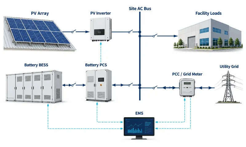
PV–BESS Electrical Interface Review Matrix
| Interface | Design evidence | Potential conflict | Required review |
|---|---|---|---|
| PV inverter to site network | PV inverter datasheet, approved drawings and protection information | Unclear inverter operating limits or protection coordination | Confirm the as-built or proposed PV interface and operating requirements |
| BESS PCS to electrical bus | PCS ratings, connection drawing, switchgear data | Insufficient current capacity, unsuitable equipment ratings or incorrect connection assumptions | Check the proposed tie-in through a site-specific electrical study |
| Transformer and switchboard | Equipment nameplates, existing SLD and applicable studies | Unreviewed bidirectional power flow or protection changes | Confirm the allowable operating envelope and any required modifications |
| Utility PCC | Interconnection agreement and utility correspondence | Combined export exceeding approved conditions | Confirm utility limits, approval conditions and the responsible applicant |
| Metering and CTs | Metering schematic, CT orientation and data-point schedule | Controller sees incomplete or incorrectly signed power flow | Confirm measurement at the boundary used by export control |
| Protection and disconnection | Protection study, settings schedule and device information | Uncoordinated tripping or incorrect islanding response | Review the required protection behavior for the approved operating modes |
| Control and auxiliary interfaces | I/O list, communications diagram and auxiliary-power requirements | Missing signals, incompatible protocols or loss of control power | Assign signal mapping, interface testing and fallback responsibility |
Do not assume that a PV inverter and battery PCS can communicate simply because both support a common protocol. The actual register map, permissions, polling behavior, gateway requirements and firmware versions may still differ. Likewise, the contribution of inverter-based equipment to a fault must be evaluated using the equipment's documented fault response rather than a generic fault-current assumption.
Interconnection requirements vary with the utility and jurisdiction. The US Department of Energy's Distributed Energy Interconnection Checklist provides a useful framework for organizing questions and tasks across the interconnection process; project-specific approval remains with the relevant parties.
Confirm Charging, Export and Operating Controls
The PV inverter, battery PCS and site controller may be supplied by different companies. Before commissioning, the control design needs one agreed source of dispatch authority, a defined metering boundary and documented behavior when equipment becomes unavailable. The energy management system (EMS) is central to this coordination, but it does not replace PCS local limits, battery protection or utility-required protection functions.
Charging rules are project-specific. Some sites permit grid charging, others impose restrictions linked to a utility program, contract or operating objective. Similarly, excess solar generation may be exported, curtailed or handled through another approved operating mode. No one response should be presented as universal.
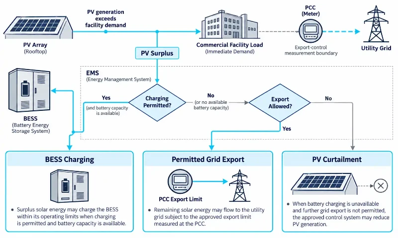
Combined Operating Scenario Matrix
| Scenario | Behavior to define | Evidence to request | Review owner |
|---|---|---|---|
| PV generation exceeds facility demand | How charging, permitted export and PV curtailment are prioritized | Energy-management control narrative and site power-flow diagram | Controls integrator and owner |
| Battery reaches its upper permitted SOC | How the controller responds when further charging is unavailable | High-SOC operating sequence and PV dispatch interface | BESS and PV control parties |
| Grid export approaches its approved limit | Which meter governs control and how export is constrained | Metering arrangement, setpoint ownership and approved test criteria | Electrical engineer and controls integrator |
| PV production falls while site demand rises | How BESS dispatch changes within its available power and energy limits | Operating-mode description and PCS/BMS limits | System integrator |
| BESS becomes unavailable | How PV and facility controls continue without relying on storage | Loss-of-BESS response and alarm routing | Owner and controls integrator |
| Communications are interrupted | Approved fallback behavior for each affected device and reconnection conditions | Communications-failure matrix and device manuals | Relevant equipment suppliers and integrator |
| Utility supply is lost | Grid-connected shutdown behavior, or a separately designed backup sequence if specified | Protection design and approved operating-mode documents | Electrical engineer and owner |
Control response time, meter sampling and export-limit tolerance must come from the approved design and utility requirements. They should not be replaced with arbitrary millisecond targets. Software export control and protective disconnection also serve different purposes; either may be subject to separate approval or testing requirements.
If the project includes backup operation, the design must identify the supported loads, isolation arrangements, suitable grid-forming or other required equipment capabilities, and approved transfer and protection sequence. A conventional grid-connected commercial solar battery system should not be assumed capable of powering a site during a utility outage.
Review Safety and Permitting Evidence
Safety approval depends on the location, installation conditions and exact equipment supplied. Procurement teams should verify the certification or conformity evidence that applies to the target market and to the proposed BESS configuration. A cell or module certificate alone is not a substitute for system-level evidence where that evidence is required.
For projects subject to relevant US requirements, UL Solutions' overview of ESS testing and certification explains UL 9540 as a system-level safety standard. UL 9540A, by contrast, is a test method for evaluating thermal-runaway fire propagation, not a stand-alone system certification. The applicable NFPA 855 edition, fire-code provisions, test evidence and installation conditions must be confirmed for the actual jurisdiction and authority having jurisdiction (AHJ).
| Safety or permit item | Evidence to review | What to confirm |
|---|---|---|
| Product conformity | Certificates, listings or declarations relevant to the target market | The documents apply to the proposed models and system configuration |
| Fire propagation assessment | Applicable test reports and supporting installation guidance | Evidence supports the proposed arrangement and any required mitigation |
| Equipment layout | Site plan, equipment location and service-access drawings | Local installation, access and separation requirements are addressed |
| Environmental conditions | Temperature, exposure, drainage and enclosure information | The installation is within the equipment's documented operating limits |
| Electrical isolation and protection | Approved one-line and protection diagrams | PV and BESS disconnects, isolation and interlocks have defined functions |
| Emergency information | Response plan, equipment instructions and site contacts | Operators and responders have the required site-specific documentation |
| Authority submission | Permit register and utility correspondence | Someone is assigned to submit documents and resolve outstanding comments |
Do not treat a test result as a universal cabinet-spacing rule, or assume every commercial PV+BESS project worldwide must comply with the same US standards. The applicable requirements should be agreed early enough that a late permitting decision does not force changes to the equipment layout.
Check Installation and Deployment Constraints
PV and BESS projects often involve separate installation crews and equipment suppliers. This makes the interface boundary as important as the physical equipment delivery. The installation plan should name who provides each external cable, conduit, communication link, metering component and tested connection.
Site and Construction Interface Checks
- Equipment location: Confirm the BESS footprint, delivery path, handling method, maintenance access and environmental exposure against the approved layout.
- Electrical route: Confirm the planned path and termination boundaries from the BESS equipment to the designated site electrical connection, including any interfaces with existing PV circuits.
- Existing PV operations: Identify whether construction, metering changes or control commissioning will affect PV availability, site loads or both.
- Communication infrastructure: Assign responsibility for network hardware, fiber or copper cabling, gateways, cybersecurity access and protocol documentation as relevant.
- Construction sequence: Coordinate foundation readiness, equipment delivery, electrical tie-in, inspections, controller configuration and approved outage windows.
- Drawing control: Define who updates the single-line diagram, meter and CT plan, network topology, protection settings and final as-built package.
The choice between an outdoor cabinet BESS and a larger equipment arrangement may change footprint, delivery and service-access requirements. Those physical differences should be checked against the specific product drawings rather than inferred from a category name.
Who Supplies and Approves Each Interface?
| Interface or deliverable | Party to assign in the contract | Acceptance evidence |
|---|---|---|
| BESS equipment and internal factory-installed interfaces | BESS OEM or equipment supplier, as contracted | Approved equipment schedule and factory documentation |
| PV inverter information and required control access | PV OEM, PV contractor or existing system owner | Verified model details, signal list and interface permissions |
| AC tie-in, protection and field wiring | Electrical designer and installation contractor | Approved drawings, inspection and test records |
| EMS integration, commands and alarms | Named controls integrator | Control narrative, I/O mapping and integration test results |
| Permits, utility submissions and witness scheduling | Project developer, owner or appointed representative | Authority correspondence and completed approval register |
| Integrated site testing and handover | Commissioning lead with all affected suppliers | Accepted procedures, results, exceptions and as-built records |
These are responsibilities to allocate, not universal descriptions of what every manufacturer or EPC automatically includes. The contract should explicitly state who is responsible for third-party inverter compatibility, onsite configuration, witness testing and corrections if the combined system fails an agreed test.
Define Integrated PV + BESS Acceptance Tests
A BESS factory acceptance test (FAT) can confirm the equipment and functions covered by that test. It cannot by itself establish that the installed battery will coordinate with a particular PV inverter, utility meter and site control system. Those combined behaviors require site acceptance testing (SAT) and any additional utility or authority witness testing required by the project.
Joint Operating Test Matrix
| Test scenario | What should be demonstrated | Acceptance record |
|---|---|---|
| PV operating, BESS idle | PV continues in its approved operating mode without unintended BESS dispatch | Power, meter and controller logs |
| Permitted battery charging | Charging follows the approved source rules and device limits | Operating-mode record and metering data |
| Combined PV and BESS dispatch | Control priorities remain consistent as PV output and facility demand change | Joint system performance trace |
| Approved export limitation | Measured exchange at the defined PCC remains within the approved test criteria | Meter records, test conditions and controller response evidence |
| High battery SOC | PV output, permitted export and any curtailment follow the defined control sequence | Test result against the control narrative |
| Controller or network fault | Relevant devices enter their documented and approved fallback states | Fault logs, alarms and recovery record |
| Protective and emergency interfaces | Required alarms, interlocks and protective actions respond under approved test procedures | Inspection and witnessed test sheets |
| Backup or islanded operation, if in scope | The approved transfer, isolation and operating sequence performs as specified | Separate approved test record |
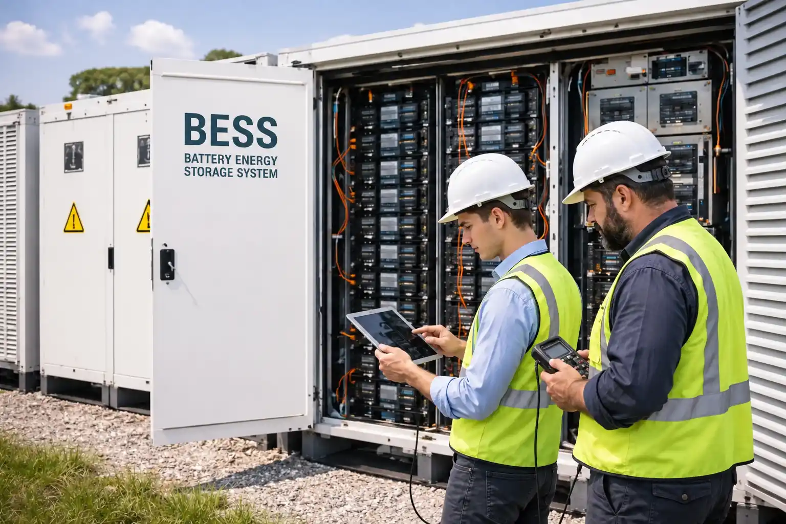
Specify each test's initial conditions, measured points, pass/fail criteria and witnesses before the site test begins. Do not use an invented response-time threshold or assume that an emergency stop test alone demonstrates complete PV and battery protection coordination. Where a test could interrupt production or involve electrical hazards, the responsible qualified personnel must follow the approved site procedure.
Handover should include the as-built drawings, final control and protection settings, operating-mode descriptions, access and configuration records as appropriate, open-item register, test results, manuals and agreed service responsibilities. If an item remains outstanding, record whether it prevents operation or is accepted under a documented closeout plan.
Commercial Solar Battery Storage Deployment Checklist
The following matrix can be used at design review, procurement release and pre-commissioning meetings. The entries are review prompts, not records showing that a specific project has already passed. Record each item's status as Verified, Pending or Not Applicable, with supporting evidence and an assigned decision-maker.
| Review item | Required document or evidence | Unresolved issue | Approval owner | Release status |
|---|---|---|---|---|
| PV and facility design basis | PV schedule, load data, site operating specification | Inconsistent or missing design assumptions | Project engineer | To confirm |
| Electrical connection and equipment ratings | Approved SLD and required electrical studies | Unverified combined operating envelope | Electrical design authority | To confirm |
| PCC export and interconnection | Utility agreement, meter/CT drawing | Unapproved or unmeasurable export-control boundary | Owner and utility applicant | To confirm |
| PV–BESS control interface | Inverter details, protocol map, control narrative | Incompatible or unassigned command interfaces | Controls integrator | To confirm |
| Charging and fallback modes | Operating scenario matrix and device limits | Unspecified response to full SOC or lost communications | Owner and controls integrator | To confirm |
| Safety and authority review | Applicable product evidence, site plan and permit register | Missing approval or unsupported installation arrangement | Permitting lead | To confirm |
| Site and contractual interfaces | Access plan, work schedule, responsibility matrix | Unassigned cables, works or test support | EPC/project manager | To confirm |
| Integrated commissioning | SAT procedure, witness list and acceptance criteria | PV and BESS have not been proven to operate together | Commissioning lead | To confirm |
| Final handover | As-builts, results, settings, manuals and open-item register | Incomplete operating documentation | Owner's authorized representative | To confirm |
Not every pending item blocks every stage. A missing final as-built drawing, for example, is different from an unapproved grid connection or undefined protective function. The owner and design authority should set specific release gates for procurement, site installation, energization and final acceptance.
What Should EPCs and Buyers Include in the RFQ?
A request for quotation should describe how the proposed commercial solar battery storage equipment must fit the actual project. Sending only a target kW and kWh figure leaves the supplier to make assumptions about electrical interfaces, export control, monitoring and delivery scope.
- PV system details: Existing or proposed PV power ratings, inverter manufacturers and model numbers, topology and relevant drawings.
- Electrical interface: Site single-line diagram, candidate BESS connection point, grid service and equipment ratings, metering arrangement and known protection requirements.
- Operating specification: Intended charge sources, dispatch priorities, export restrictions, SOC reserve and any defined backup duty.
- Controls and communications: EMS ownership, required signal list, available protocols, register maps, gateways, access requirements and failure behavior.
- Project environment: Proposed equipment location, access route, ambient conditions, delivery constraints and site-specific restrictions.
- Compliance evidence: Destination market, applicable approvals and documents required for the exact quoted configuration.
- Scope split: Clarification of equipment supply, external wiring, controller integration, configuration work, site testing and corrective action responsibilities.
- Handover expectations: Required FAT/SAT support, drawings, operating documents, warranty conditions, training and service interfaces.
The US Department of Energy's lithium-ion BESS technical specifications template is one useful reference for structuring a project-specific technical request. Its contents should be adapted to the actual project rather than adopted as an automatic requirement for every country.
For a project being discussed with Polinovel, begin with the available PV inverter information, electrical single-line diagram, site load and export requirements, preferred operating modes and destination market. That gives the equipment team a clear basis for reviewing possible commercial and industrial energy storage configurations and identifying interfaces that still require confirmation. Product features, certification coverage and commissioning support must be checked against the configuration and quotation actually offered.
Frequently Asked Questions
What should be checked before adding batteries to an existing commercial solar system?
Start with the current PV inverter details, site single-line diagram, main distribution and transformer information, meter locations, facility demand data and the utility interconnection agreement. The project team should then confirm the proposed PCS tie-in, protection, control interfaces and installation approvals. A PV system's existing approval may not automatically cover a new BESS.
Can a commercial BESS charge from both solar and the grid?
It may be technically possible, but the permitted charging sources depend on the selected architecture, product capabilities and project requirements. Utility programs, contracts or other applicable conditions may restrict charging behavior. The approved control strategy should identify the permitted sources and how they will be verified.
What happens when the battery is full and PV output exceeds site demand?
Once further charging is unavailable, the design must specify what happens to the excess PV output. Depending on utility permissions and equipment controls, the system may export permitted power, curtail PV generation or use another approved operating arrangement. A site with a no-export condition needs a tested control response at the relevant measurement boundary.
Who is responsible for PV inverter and BESS EMS compatibility?
The project contract should name the integration party and the equipment suppliers responsible for providing protocol documents, access rights and support. Compatibility must be demonstrated against the installed inverter model, software version and required command or monitoring points. A general claim of protocol support is not enough.
Which safety documents should an EPC request?
Request evidence appropriate to the destination market and the exact proposed BESS configuration, together with relevant fire-test information, installation instructions, site layouts, electrical protection documents and emergency-response materials. In US projects, UL 9540 system certification and UL 9540A thermal-runaway test evidence may be relevant under the applicable code and authority requirements, but the two are not interchangeable.
What must be tested before commercial operation?
Alongside the required equipment and electrical inspections, the site team should verify combined PV and BESS operation, permitted charging, export limits, high-SOC response, communications fallback, alarm reporting and approved protective interfaces. Backup or islanded operation needs separate testing only when included in the project design. Acceptance criteria must be established before testing.
Does every solar-plus-storage project require grid-forming capability?
No. A grid-connected PV+BESS project does not automatically need grid-forming operation. If the owner requires an islanded or backup operating mode, the necessary inverter capability, isolation, protection and control architecture must be separately specified and approved. A battery cabinet alone does not establish that functionality.
Conclusion
Commercial solar battery storage deployment depends on more than the battery specification. The PV and PCS connections, utility interface, dispatch controls, safety documents and combined acceptance tests all need a clear design basis and an assigned owner. Before equipment is released, the EPC and project buyer should be able to show which interfaces are verified, which remain open and who is responsible for closing them.
Providing the solar inverter schedule, site drawings, operating requirements and approval conditions at the RFQ stage makes those discussions specific. It also helps distinguish an equipment proposal that fits the intended project from one that still relies on untested assumptions.